2 on front mounted leds, 1 exceptions/special conditions for the leds – Nevion HD-TD-10GMX-6 User Manual
Page 13
HD-TD-10GMX-6 / HD-TD-10GDX-6
Rev. B
nevion.com | 13
Each channel also has its own error bit indicators. The boxes that have a red background
color indicate an error that is currently detected and counted. A green background will
indicate that the particular error is set to be counted, but that the error is currently not
detected. Errors that are not to be counted (i.e. set to Ignore) will be presented as the error
bit name on a gray background color (no example shown here), regardless if the error is
currently detected or not. Error types that are not supported for that particular channel will
be shown as blank boxes with gray backgrounds. Most web browser will expand the boxes
that contain text at the expense of these blank ones, as the examples above show.
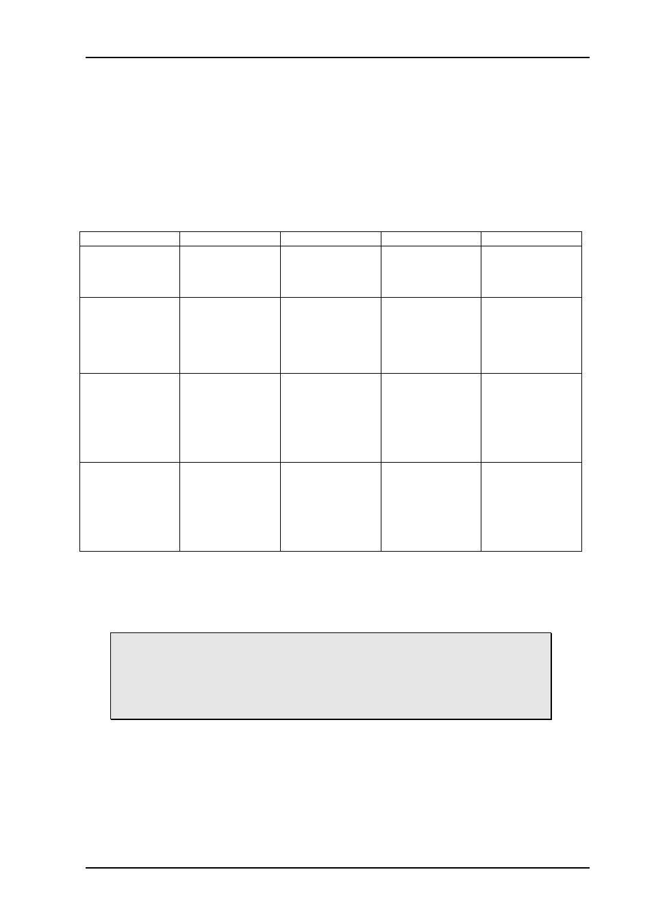
4.2 On front mounted LEDs
Table 2: LED states and what they mean
The LEDs on the board are not labeled in silk screen. Users familiar with the Flashlink
range will know that the upper LED (closest to the red handle) is the status LED. The order
of the rest of the LEDs corresponds to the order in the table above.
Note that the configuration of the Expected video format will influence the way
the LEDs behave.
The “Don’t care” condition mentioned in the table above
refers to the “Expected video format” settings, and only those channels
assigned a specific video format will affect the LEDs. Conversely, setting all
channels to “Don’t care” will result in LED 3 and LED 4 always being green,
even if all video signals are missing.
4.2.1 Exceptions/special conditions for the LEDS
The locate command will make all four LEDs blink on and off synchronously to quickly
identify the module in a larger installation. The condition of the card is not otherwise
affected by the command, only the appearance of the LEDs will change. The LEDs return to
their normal states and functions after the special locate condition has timed out.
Red LED
Orange LED
Green LED
No light
Card status
FPGA not loaded,
or at least one
voltage outside
legal levels
---
Module is OK
Module has no
power
Mux: Laser
De-mux: Pin
Laser missing or
failed
Input missing or
signal below -28
dBm
Laser present but
turned off
Input signal below
-25 dBm
Laser present
and turned on
Input signal
stronger than
-25 dBm
Module has no
power
Inputs 1-4
At least one of
the channels 1-4
that are not set to
Don’t care is
missing lock
At least one of the
channels 1-4 that
are not set to
Don’t care is
locked to the
wrong video
format
Channels 1-4 are
all either set to
Don’t care or are
present and have
the right video
format
Module has no
power
Inputs 5-8
At least one of
the channels 5-8
that are not set to
Don’t care is
missing lock
At least one of the
channels 5-8 that
are not set to
Don’t care is
locked to the
wrong video
format
Channels 5-8 are
all either set to
Don’t care or are
present and have
the right video
format
Module has no
power