4 expected video format – Nevion HD-TD-10GMX-6 User Manual
Page 9
HD-TD-10GMX-6 / HD-TD-10GDX-6
Rev. B
nevion.com | 9
indicated on the 10G stream, chances are that one or more of the outputs have also been
affected. The error bits for the fiber transport stream are limited to LOCK error and FF-CRC
error. This FF-CRC bit is not the same as FF-CRC for normal SDI video, but rather a
mapping of several internal checksums into one error bit. This error counter behaves as the
others in the sense that the error count per second is limited to slightly more than 60.
Note that when an input is missing, only the LOCK error bit is set, not the other
error bits. Generally it is therefore a good idea to count the LOCK error bit, as
the other error bits will indicate that everything is OK when the input signal has
indeed been lost. Individual reclocker alarms also exist, and while a single
observation of loss of lock is enough to trigger these alarms, the lock status is
only sampled when Multicon asks the card for its current status. The update
frequency will thus depend on how many other cards are in the system, and
glitches in lock status will not necessarily be reported to Multicon to trigger an
alarm there.
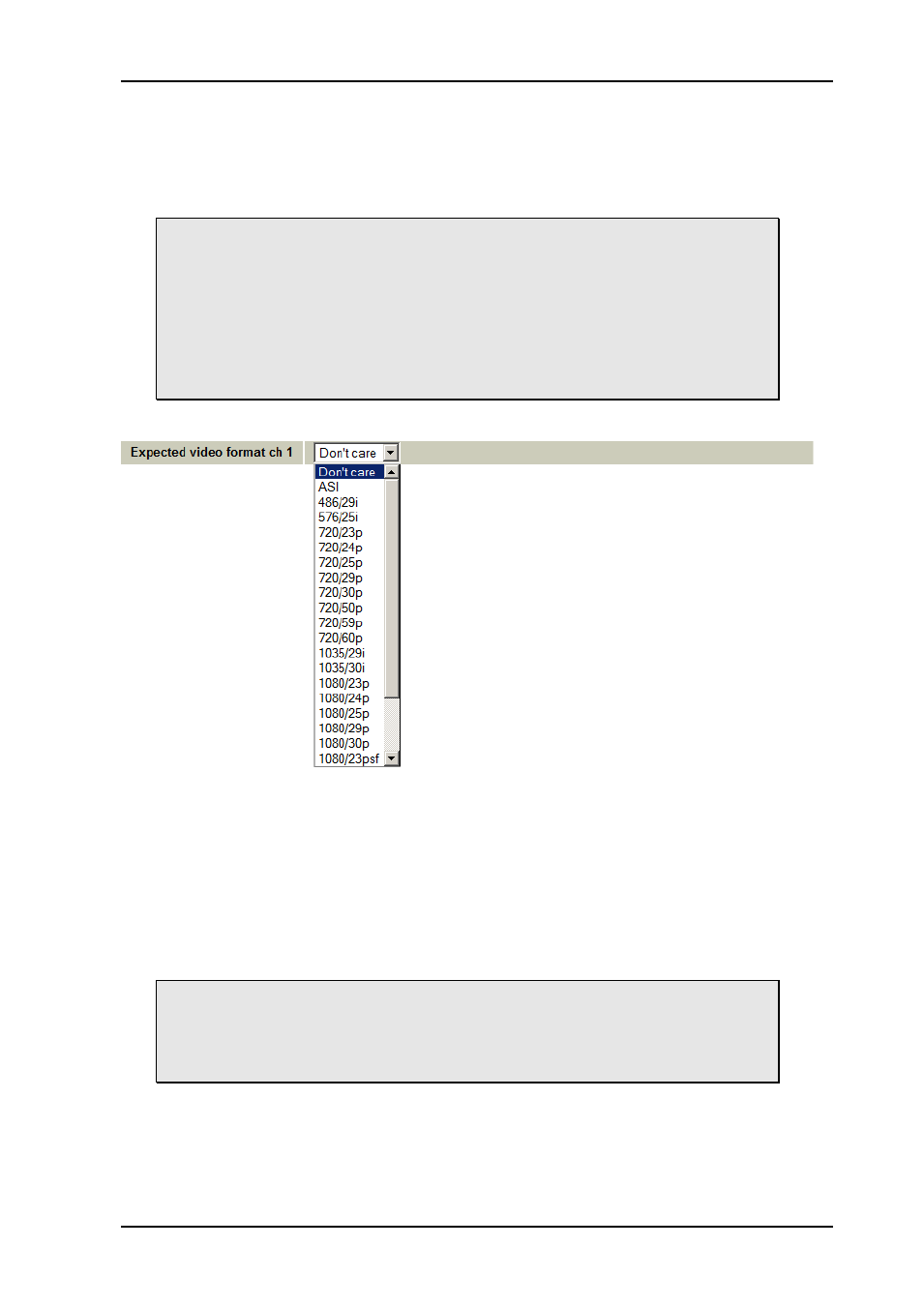
3.1.4 Expected video format
Figure 5: Selection of expected video format
In transport products like these it is not always enough to know that video is present and
error-free. It can be equally important to know that the video format is correct. The operator
can select an Expected video format for each channel. An
input or output signal that doesn’t
match its expected video format will be indicated as a VS error in Signal integrity (see ch.
3.1.3). In addition to the formats shown in the figure above, 1080/24psf, 1080/25i, 1080/29i
and 1080/30i are available in the menu if scrolled down. For channel 7 and 8 (that are
limited to 270 Mb/s) the selection of expected video format is reduced to ASI, 486/29i and
576/25i, in addition to the
Don’t care setting.
Note that in order to trigger a Signal integrity alarm, the VS error bit must be set
to Counted and the error rate set below the video frame rate. Note also that
missing video will not trigger the VS error bit. The operator should instead rely
on the LOCK error bit or the reclocker alarms to detect loss of lock. See note at
the end of ch. 3.1.3.