1 gpi connections, rj45, 3 the main board – Nevion SDI-TD-3GMX-5 User Manual
Page 27
HD-TD-3GMX-2 / HD-TD-3GDX-2 and SDI-TD-3GMX-5 / SDI-TD-3GDX-5
Rev. F
nevion.com | 27
The following connectors are available:
Name
Description
Connector Type
MUX/DEMUX
Output (Input) for 2970 Mbps 3GHD-SDI.
BNC
OPT
Optical output (input) for 2970 Mbps HD-SDI
(optional).
SC/UPC
1
Input (Output) for 1485 Mbps HD-SDI or 270 Mbps
SD-SDI.
BNC
2
Input (Output) for 1485 Mbps HD-SDI or 270 Mbps
SD-SDI.
BNC
3 (SD)
Input (Output) for 270 Mbps SD-SDI.
BNC
4 (SD)
Input (Output) for 270 Mbps SD-SDI.
BNC
5 (SD)
Input (Output) for 270 Mbps SD-SDI.
BNC
GPI I/O
General Purpose Interface.
RJ-45
Table 4: Back plane connectivity
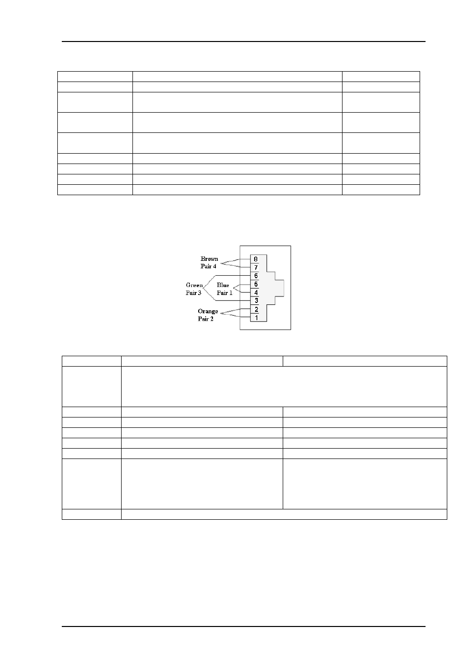
7.2.1 GPI connections, RJ45
Figure 12: Pin layout
Pin number
Multiplexer functionality
De-multiplexer functionality
1
Card OK.
This pin essentially follows the card’s status LED: When the LED is green, the pin
will indicate card OK. The pin will indicate NOT OK when the LED is yellow, that is
when the FPGA is being loaded.
2
Input 1 present
Output 1 present
3
Input 2 present
Output 2 present
4
Input 3 present
Output 3 present
5
Input 4 present
Output 4 present
6
Input 5 present
Output 5 present
7
Output OK.
This pin follows the output LED: It will
indicate OK when the output LED is
green, which is when output is present
and the laser not faulty.
Input OK.
This pin follows the LOS LED: It will
indicate OK when the LOS LED is
green, which is when input is present
and taken from the main input.
8
Ground (GND)
Table 5: GPI pin-out
The polarity of the GPI pins is such that OK/present is indicated by a leading transistor
connection to ground. Conversely, an error is indicated by high impedance to ground.
7.3 The main board
There are also a number of connectors on the board itself. None of these are intended for
the end-user.