3 normal control blocks for the dmux cards – Nevion SDI-TD-3GMX-5 User Manual
Page 33
HD-TD-3GMX-2 / HD-TD-3GDX-2 and SDI-TD-3GMX-5 / SDI-TD-3GDX-5
Rev. F
nevion.com | 33
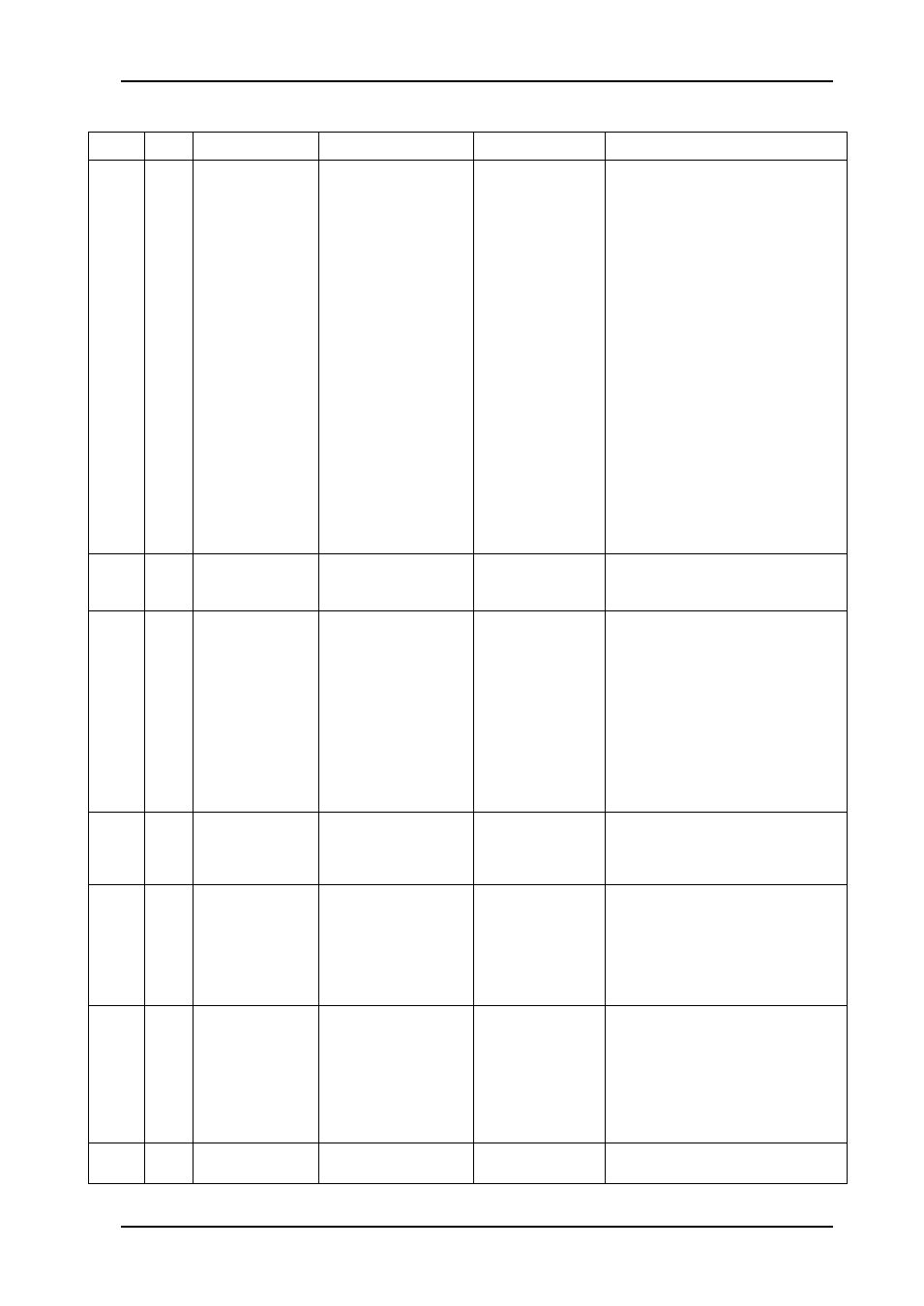
8.2.3 Normal control blocks for the DMUX cards
Block Blk#
Commands
Example(s)
Response
Control
cho
0
pri <k> |
pri <k> <l>
pos man <k> |
pos auto
latch reset
t1 <hold_time>
t2 <lock_time>
cho 0 pri 0
cho pri 0 1
cho pri 0 2
cho 0 pos man 1
cho 0 pos auto
cho 0 latch reset
cho 0 t1 1000
cho 0 t2 1000
size 3 pri k,l auto t1
<hold time> t2
<lock time>
size 3 pri k,l man m
latch t1 <hold time>
t2 <lock time>
Video input select
pri: a prioritized list of inputs, used
when change-over is automatic. The
list can have 1, 2 or 3 entries, or
levels. Manual mode is effectively the
same as automatic mode with one
priority level only, but has its own
command.
0 = from electrical input
1 = from optical input
t1 and t2: change-over doesn't
happen immediately, as a precaution
against glitches and unstable signals.
The timers t1 and t2 let the user
decide how long (in ms) we will cling
on to a missing input before we
consider it gone and move on to the
next pri level, and how long an input
with a higher priority should be
present before we consider it
repaired and switch back,
respectively.
cho
1
size 3 pri k,l auto
size 3 pri k,l man m
No commands available. Included to
show internal status and to update
Multicon GYDA graphics.
mtx
0
-
mtx 0
size 6:1 <in1>
Operating mode
mtx 0 has no valid commands, it is
only used to display the current
configuration set from the MUX side.
The values has the following
interpretations:
0: HD+HD
1: HD+SD
2: SD+HD
3: SD+SD
4: HD+4xSD
5: SD+4xSD=5xSD
pin
(0)
-
pin 0
cd | ncd
Pin diode status (DMUX only)
No control. Only used to report
carrier detected or no carrier
detected.
pwr
0-5
-
<nom>Vnom
<volt>V
Power supply monitors
pwr 0 = 15.0V
pwr 1 = 5.0V
pwr 2 = 3.3V
pwr 3 = 2.5V
pwr 4 = 1.8V
pwr 5 = 1.2V
rcl
0-5
-
rcl 0
lock | lol
Reclocker
No commands available, only used to
report lock status. The DMUX board
has one rcl block for the 3G input (rcl
0) and one rcl block for each
recovered stream (rcl 1
– rcl 5).
The 2-input cards only display 3 rcl
blocks.
vmon
0-5
reset
msk <bit_msk>
vmon 0 reset
vmon 0 msk 0x78
vmon 0 msk
<bit_mask>
Video monitor (DMUX)
The DMUX has one vmon block to