3 connections, 4 sync input – Nevion PGM-HD-2x1-PB User Manual
Page 10
PGM-HD-2x1-PB
Rev. B
nevion.com | 10
3.2.2 Configuration page
The different configuration possibilities are explained in detail in Chapter 5, under the
corresponding functions.
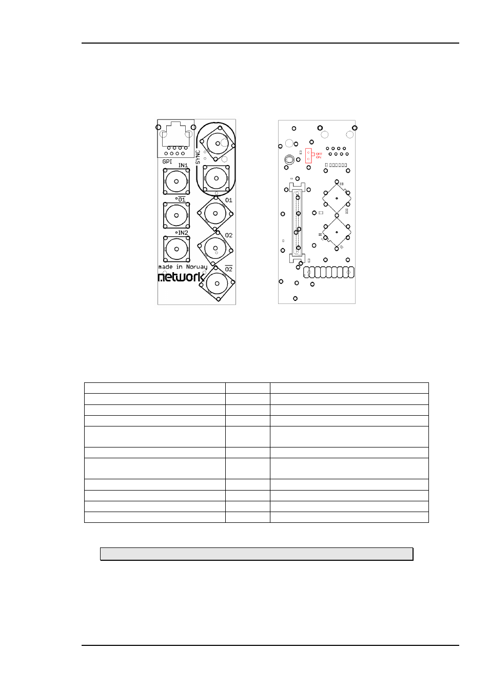
3.3 Connections
Figure 4: PGM-HD-2x1-PB backplane
right: connection side
left: component side
The backplane for the PGM-HD-2X1-PB is also labeled PGM-HD-2x1-PB. The table
below shows the connectors and their functions.
Function
Label
Connector type
HD/SD-SDI input 1
IN1
BNC
HD/SD-SDI input 2
IN2
BNC
HD/SD-SDI output 1
O1
BNC
HD/SD-SDI output 1 inverted
___
O1
BNC
HD/SD-SDI output 2
O2
BNC
HD/SD-SDI output 2 inverted
___
O2
BNC
Black & Burst/ tri-level input
SYNC
BNC
Black & Burst/ tri-level input
SYNC
BNC
GPI in
GPI
TP45, pin 5 & 6
GPI out
GPI
TP45 pin 1, 2, 3, 4, 7 (pin 8 = GND)
Table 2: Connector functions
Unused SDI inputs/outputs should be terminated with 75 Ohm.
3.4 Sync input
The two sync inputs on the backplane are internally connected together. It is possible
to use one as input and the other as a looped output. The backplane also features a
switchable termination. By setting the red switch in Figure 4 to
“on” (the lower position)
the sync input will be terminated with 75 Ohms.