3 configuration, 1 manual mode, 1 rotary switch and push buttons – Nevion PGM-HD-2x1-PB User Manual
Page 6: 2 slide switch
PGM-HD-2x1-PB
Rev. B
nevion.com | 6
3 Configuration
The board can be controlled manually via DIP switches, rotary switches and push
buttons on the board, or through the graphical user interface provided by the system
controller Multicon Gyda. Only the most frequently changed and/or most important
settings are available on the DIP switches. If Multicon is used to do an initial setup of
the other settings, these settings will be retained in the module for future sessions,
even for manual mode.
3.1 Manual mode
To reach manual mode DIP16 labeled OVR on the board must be switched on (to the
right) and the board must be re-booted. This takes the board out of Gyda control (if the
switch was previously set to off) and over to DIP switch, rotary switch and push button
control. This particular DIP switch (and the factory reset DIP switch) will only be read at
start-up. Settings not controlled by any of these manual switches/buttons are kept
unchanged from previous session (factory setup or Gyda setup).
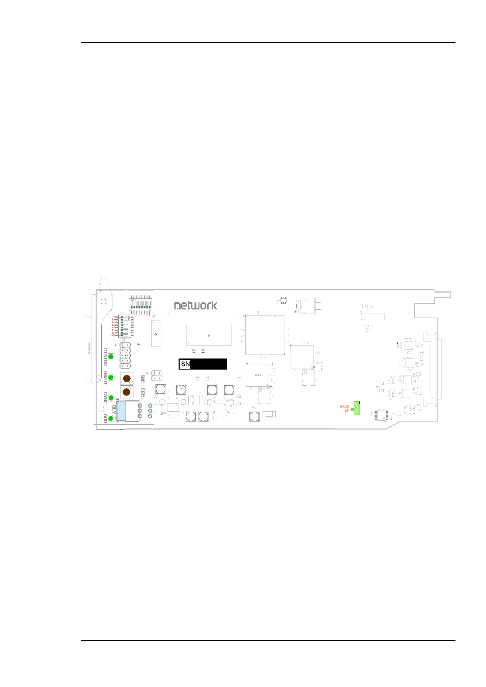
The Manual Mode configuration controls are all found on the front side of the board.
There are two sets of DIP switches, one rotary switch and two push buttons. The slide
switch on the lower right side
should be se to the lower position (“BP”) for all operation
modes.
Figure 2: The figure shows a top view component printout of the board. LEDs, push-
buttons, the rotary switch and the 2 sets of DIP-switches are colorized.
3.1.1 Rotary switch and push buttons
The rotary switch, labeled DLY, adjusts the phase delay by -5 to +4 video lines. It is
only functional when a sync signal, black & burst or tri-level, is present at the sync
input. The rotary switch is accessible from the board front.
The push buttons, labeled INC and DEC, are used to fine adjust the phase delay by
samples. It can adjust within +/- ½ video lines for the present video standard.
These settings are part of the frame synchronizer, see chapter Frame synchronizer5.4
for further explanations.
3.1.2 Slide switch
The slide switch on the lower right side of the card switches between backplane sync
input (BP) and Flashlink rack distributed sync (RACK) (Future feature upgrade of
Flashlink frame). Switch moved down routes the backplane sync to the card.