4 operation, 1 front panel led indicators, 2 gpi alarms – Nevion PGM-HD-2x1-PB User Manual
Page 11: 1 functions of 8pin modular jack, Pgm-hd-2x1-pb rev. b
PGM-HD-2x1-PB
Rev. B
nevion.com | 11
4 Operation
4.1 Front panel LED indicators
Diode \ state
Red LED
Orange LED
Green LED
No light
Card status
PTC fuse has been
triggered or FPGA
programming has
failed
Module has not
been programmed,
RESET and OVR
DIPs are on, or
module is updating
firmware.
Module is OK
Module has no
power
SDI input status
Video signal
absent.
Video signal
present but card
not able to lock
VCXO
Video input signal
in lock
Module has not
been programmed
Sync input status
Sync signal absent
Sync signal
present but card
unable to lock
VCXO
B&B or Tri-level
sync in lock
Module has not
been programmed
Audio input status
No audio
embedded in
incoming video
One, two or three
audio groups
embedded in
incoming video
4 audio groups
embedded in
incoming video
Module has not
been programmed
4.2 GPI alarms
The GPI alarms of the PGM-HD-2X1-PB are fully compatible with the HD-SDI-CHO-
2x1 module
, and thereby also the “change-over mode” of the FRS-HD-CHO (FRS-HD-
CHO can also be configured to be compatible with the FRS-HD-DMUX module). See
the table in the next sub-chapter for a detailed description.
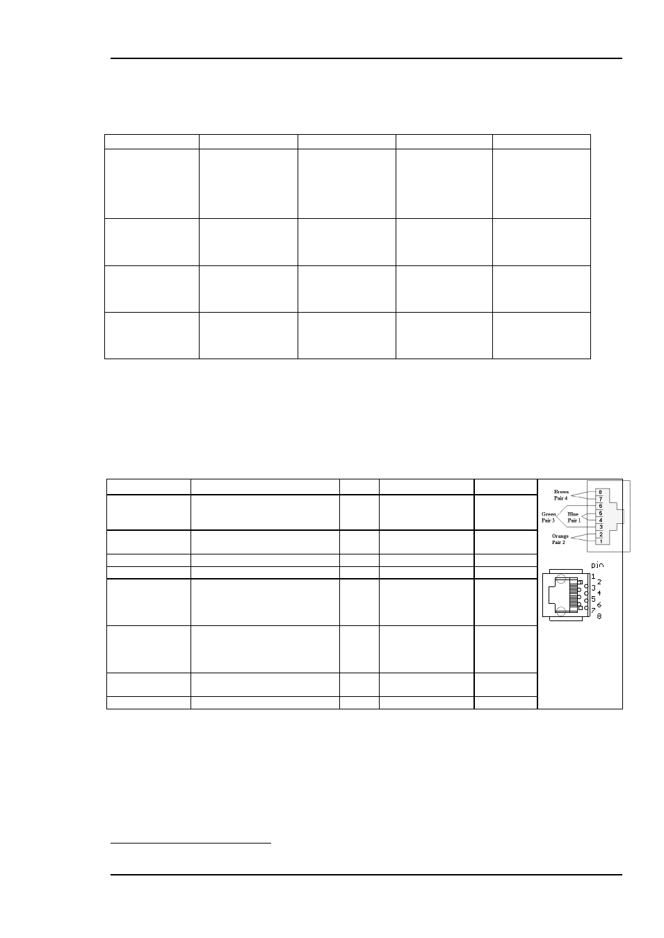
4.2.1 Functions of 8pin modular jack
GPI name
Function
Pin #
Mode
Direction
Status
General error status for the
module.
Pin 1
Inverted Open
Collector
(open is alarm)
Output
LOS
1
Loss of signal or lock at
selected input
Pin 2
Open Collector
Output
Input 1 selected
Input 1 selected (IN1)
Pin 3
Open Collector
Output
Input 2 selected
Input 2 selected (IN2)
Pin 4
Open Collector
Output
Select input 1
Fade in input 1, after fade out
of input 2. Activating
simultaneously as pin 6 will
give fade to black.
Pin 5
TTL, 0V = active
level
Input
Select input 2
Fade in input 2, after fade out
of input 1. Activating
simultaneously as pin 5 will
give fade to black.
Pin 6
TTL, 0V = active
level
Input
Input 2 selected
Connected to pin 4 on
backplane
Pin 7
Open Collector
output
Ground
0 volt pin
Pin 8
0V.
1
EDH errors will not be shown at GPI output.