3 factory reset function, 4 dip switch functions, Pgm-hd-2x1-pb rev. b – Nevion PGM-HD-2x1-PB User Manual
Page 7
PGM-HD-2x1-PB
Rev. B
nevion.com | 7
3.1.3 Factory reset function
The factory reset puts the card back to its initial settings at delivery. These settings are
just a start condition for the board, and new settings done by the user will still take
effect and be stored.
The factory reset is done by setting DIP 15 and 16 to on and power up the card. The
inputs should be removed. Then, pull out the card, put DIP 15 to off and power up the
card again. The card will now reset. The board must be under power for at least 10
seconds for all the factory reset values to be stored for the next session.
3.1.4 DIP switch functions
The two sets of DIP switches are labeled with a number running from 1 to 15. The 16
th
DIP is labeled OVR.
Note that the left DIP switch of the horizontal DIP package is number 1.
The top DIP switch of the vertical DIP package is number 9.
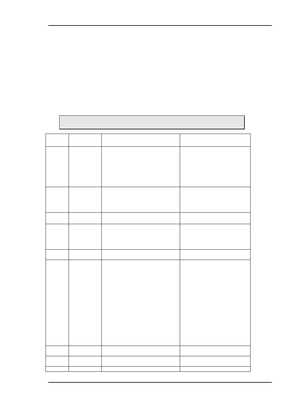
Switch
#
Function
name
Function of DIPs
Comment
1-3
Frame delay
DIP[1 2 3] = [Off Off Off] => 0 frms
DIP[1 2 3] = [Off Off On] => 1 frms
DIP[1 2 3] = [Off On Off] => 2 frms
DIP[1 2 3] = [Off On On] => 3 frms
DIP[1 2 3] = [On Off Off] => 4 frms
DIP[1 2 3] = [On Off On] => 5 frms
DIP[1 2 3] = [On On Off] => 6 frms
DIP[1 2 3] = [On On On] => 7 frms
With a sync-input present, this
sets the minimum frames delay.
Without a sync-input present, this
sets the no. of frames delay
relative to the input.
4-5
Lock & Hold
time
DIP[5 6] = [Off Off] => Minimum
DIP[5 6] = [Off On] => 1s
DIP[5 6] = [On Off] => 4s
DIP[5 6] = [On On] => Reserved
The time a signal must be
registered before it is considered
present (lock time), or the time it
can be not registered before it is
considered missing (hold time).
6
Audio gen
Off = 1kHz Sine
On = Black sound
Fallback for embedded audio
when input not present.
7
Emb. enable
Off: No audio embedded
On: Audio embedded
When off, the audio is left un-
touched on the SDI stream.
When on, the audio configured to
be embedded is embedded into
the SDI.
8
GPIO setup
Off: SDI-CHO-2x1 mode
On: FRS-HD-SDI mode
See the GPI input output
description below.
9 - 11
Fade frames
DIP[9 10 11] = [Off Off Off] => 0
frms
DIP[9 10 11] = [Off Off On] => 15
frms
DIP[9 10 11] = [Off On Off] => 30
frms
DIP[9 10 11] = [Off On On] => 45
frms
DIP[9 10 11] = [On Off Off] => 60
frms
DIP[9 10 11] = [On Off On] => 75
frms
DIP[9 10 11] = [On On Off] => 90
frms
DIP[9 10 11] = [On On On] => ***
frms
The number of frames used to
perform a fade-in or fade-out.
The same value will be used for
all four fade timers, all fading will
be symmetrical. The value for
Additional black frames will not
be modified, i.e. the value from
the previous Multicon GYDA
controlled session will be
preserved. The default is 0
frames.
The special condition [On On On]
will not modify the fade timers at
all. This setting can be used to
preserve asymmetric fade
configurations from Multicon
Gyda even in manual mode.
12
SDI OUT 1
Off: through mode
On: processed mode
In through mode the video only
goes through a re-clocker.
13
SDI OUT 2
Off: through mode
On: processed mode
In through mode the video only
goes through a re-clocker.
14
Video
Off: Color bar
This is the video generator signal