2 64x64 versions – Nevion VikinX Sublime series Rev.G User Manual
Page 10
VikinX Sublime Optical Routers
Rev. G
nevion.com | 10
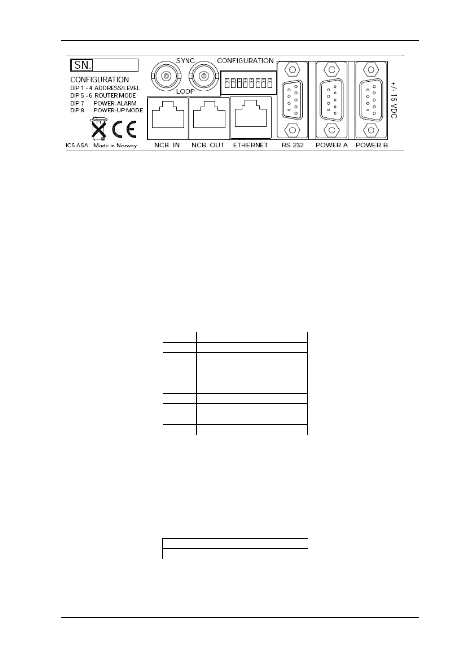
Figure 1: Service connectors.
SYNC:
Synchronization signal (in). Black burst/composite/tri-level sync
reference input with passive loop-through for vertical interval
switching.
LOOP:
Synchronization signal (out). Loop-through of SYNC input.
NCB IN:
Network Control Bus Input. The protocol of this bus is described in a
separate manual.
NCB OUT:
Network Control Bus Output.
ETHERNET:
10/100Base-T Ethernet bus for external router control.
RS 232:
RS-232 for external control protocols.
POWER A:
±15VDC power socket.
POWER B:
±15VDC power socket, redundant supply.
CONFIGURATION:
Configurations switch. See Chapter 3 for further descriptions.
2.5.1.1 Power Supply pin-out
The DE9 male sockets for the power connection on Sublime routers and Control Panels
have the following pin-out;
Pin #
Description
1
GND
2
Not connected
3
Not connected
4
+15VDC
5
Not connected
6
Not connected
7
Not connected
8
-15VDC
9
Not connected
2.5.2 64x64 versions
The 64x64 Sublime routers with optical I/O have the same service connections on the rear
of each product, as above, except for the power connectors:
Power A (48 VDC):
+48VDC power connector
3
.
Power B (48 VDC):
+48VDC power connector, redundant supply
4
.
2.5.2.1 Power Supply pin-out
The DSUB 2V2P power sockets for Sublime routers using SL-PWR-300 have the following
pin-out;
Pin #
Description
Socket +48VDC
3
Note that any VDC supplies with output voltage between +36VDC and +72 VDC, with sufficient power, may be applied to the
router.
4
The router is supplied with inverse diodes. This means that in a redundant power supply application the router will pull its
entire load from the PSU with the highest output voltage.