3 termination plug, 4 control bus structure, 5 maximum distance between ncb devices – Nevion VikinX Sublime series Rev.G User Manual
Page 27
VikinX Sublime Optical Routers
Rev. G
nevion.com | 27
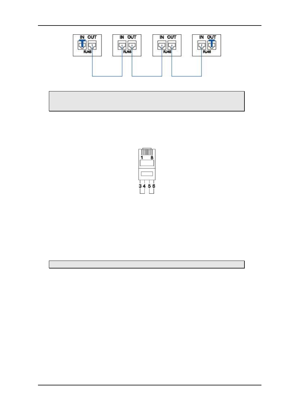
Figure 4: NCB loop configuration.
Note that each device at the end of the chain has a termination plug, indicated
with the letter “T”. This termination plug must be inserted in the correct
connection port. If not, no NCB communication is possible.
5.3.3 Termination plug
The termination plug that is mentioned in the previous chapter is necessary when you want
to avoid closing the loop be a (long) cable.
The termination plug is a standard RJ45 plug with the following internal wiring:
Figure 5: NCB loop termination plug.
As seen in the figure above, Pin 3 is connected to Pin 4, and Pin 5 is connected to Pin 6.
5.3.4 Control bus structure
The Network Control Bus structure follows the standard MIDI bus definition. The NCB is
defined as a closed chain of units. This means that the NCB OUT of the last unit must be
connected to the NCB IN of the first unit in the NCB chain. To avoid problems with the
control of VikinX units the installer/user has to assure that the bus structure is installed
according to this definition.
The total number of VikinX devices in an NCB chain is limited to 50.
5.3.5 Maximum distance between NCB devices
The standard MIDI definition allows a maximum cable length of 200-250 meters between
two devices. Longer distances can be made with MIDI repeater units. To avoid grounding
problems all NCB ports have opto-coupled inputs.