Nevion SD3232M User Manual
Page 12
Modular 3G SD Video Rev. E
nevion.com | 12
There is a switch on the right hand side of the power supply module that selects
mains voltage. The mains voltage can be either 110VAC or 230VAC. This switch
must be set in the correct position, depending on the mains voltage on the
router’s site.
Failing to select correct AC mains voltage properly may damage the power
supply unit.
If the frame is equipped with a single power supply module, only one AC mains connection is
used. However, if the frame is equipped with dual, redundant power supply modules, both
AC mains connectors must be used, preferably from two different mains circuits.
DC battery power is connected to the frame with screw terminals.
If the frame is equipped with a single power supply module, only one DC battery connection
is used. However, if the frame is equipped with dual, redundant power supply modules, both
DC battery connectors must be used, preferably from two different battery circuits.
A combination of dual, redundant power supply, using both an AC mains and a DC battery, is
possible. The frame must then be equipped with a power supply module of each type, and
one AC connector and one DC connector must be used.
3.3.4 Status LEDs and relay contacts
The Status LED indications on AC PSU modules are slightly different from those of DC PSU
modules.
There are 2 LEDs on the front of each power supply module, and they indicate the following:
AC PSU modules:
Upper, RED LED:
Normally OFF. If it is ON, there is a power supply failure, indicating
that the power supply module must be replaced.
Lower, GREEN LED:
Normally ON. If it is OFF, there is no mains power supplying the
frame.
DC PSU modules:
Upper, RED LED:
Normally OFF. If it is ON, there is a faulty output voltage, indicating
that the power supply module must be replaced.
Lower, GREEN LED:
Normally ON. If it is OFF, there is no input power supplying the
frame.
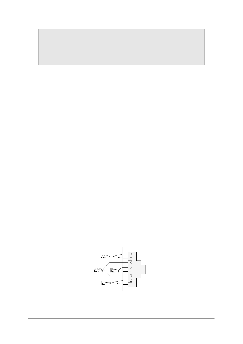
There are also two Power fail alarm relay contacts on the rear side of the frame; see
Chapters 2.1.1 and 2.5 for details. Each installed PSU module has a separate pair of
contacts. The relay contact is normally open, and the contact closes on power failure.
The PSU module A alarm is formed by contact between Pin 3 and Pin 6 (Green pair)
The PSU module B alarm is formed by contact between Pin 1 and Pin 2 (Orange pair)