U12 bluebird ka24de installation – NIStune Type 2 V.1.6 User Manual
Page 13
Advertising
Type 2 Hardware Installation Manual
Page 13 of 20
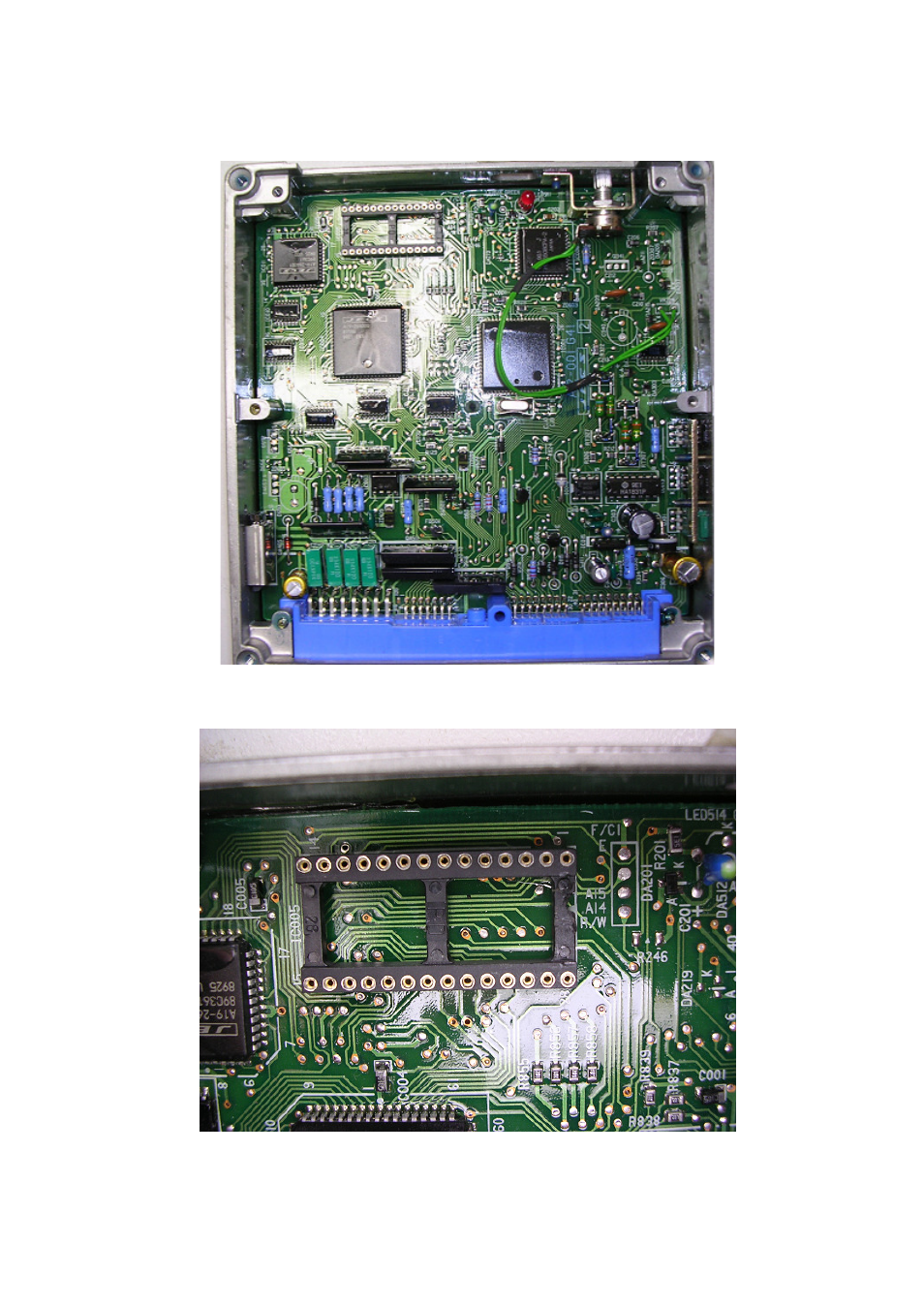
4. U12 Bluebird KA24DE Installation
Please Refer to the Z32 300ZX Installation
Figure illustrates installation of installed 28 pin socket
Desolder the four pads next to the EPROM socket where marked F/CI
Where you have desoldered the four pads, solder in the supplied connector cable. The plastic
connector has a number '1' on it. This corresponds to pin R/W of the connector. Make sure that you
solder in the cable in the correct direction
Advertising