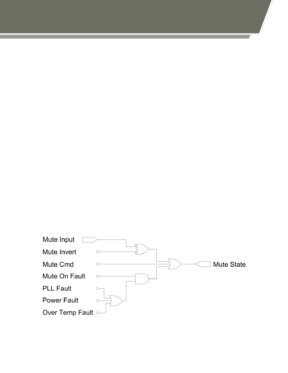
Figure 4: standard mute state logic, 3 controlling atom devices – Norsat ATOMControl User Manual
Page 18
- 16 -
An ATOM Series device’s Mute State is controlled by one hardware input signal, four
user-controllable software parameters, and three fault indicators. ATOMControl monitors
the values of all of these and displays them in the Mute Tab of the User Interface.
The signals are:
Mute Input:
The hardware input line corresponding to pin D of the MIL-C-
26482 control interface
Mute Invert:
Determines which value of the Mute Input line represents
Mute and which value represents Unmute
Mute Bias:
Determines the value of the Mute Input line if the hardware
input is left floating
Mute Command: Software mute setting
Mute On Faults:
Indicates whether the device will be muted if a fault is
detected
Muting can thus be caused by three potential sources: a hardware-based mute triggered
through the Mute Input hardware signal, fault-based muting triggered by one of three
faults, and software-based muting triggered using the Mute Command parameter.
Software-based muting will override both fault-based muting and hardware-based
muting. Fault-based muting will also override hardware-based muting.
The hardware signal, four software parameters, and three faults interact with each other
to produce the overall Mute State in one of two ways. While most devices will use the
Standard Mute Logic shown in Figure 4, some 100W devices (running firmware version
1.1.0.1 or higher) will use the Revised Mute Logic shown in Figure 5.
Figure 4: Standard Mute State Logic