Figure 5: revised mute state logic, 3 controlling atom devices – Norsat ATOMControl User Manual
Page 19
- 17 -
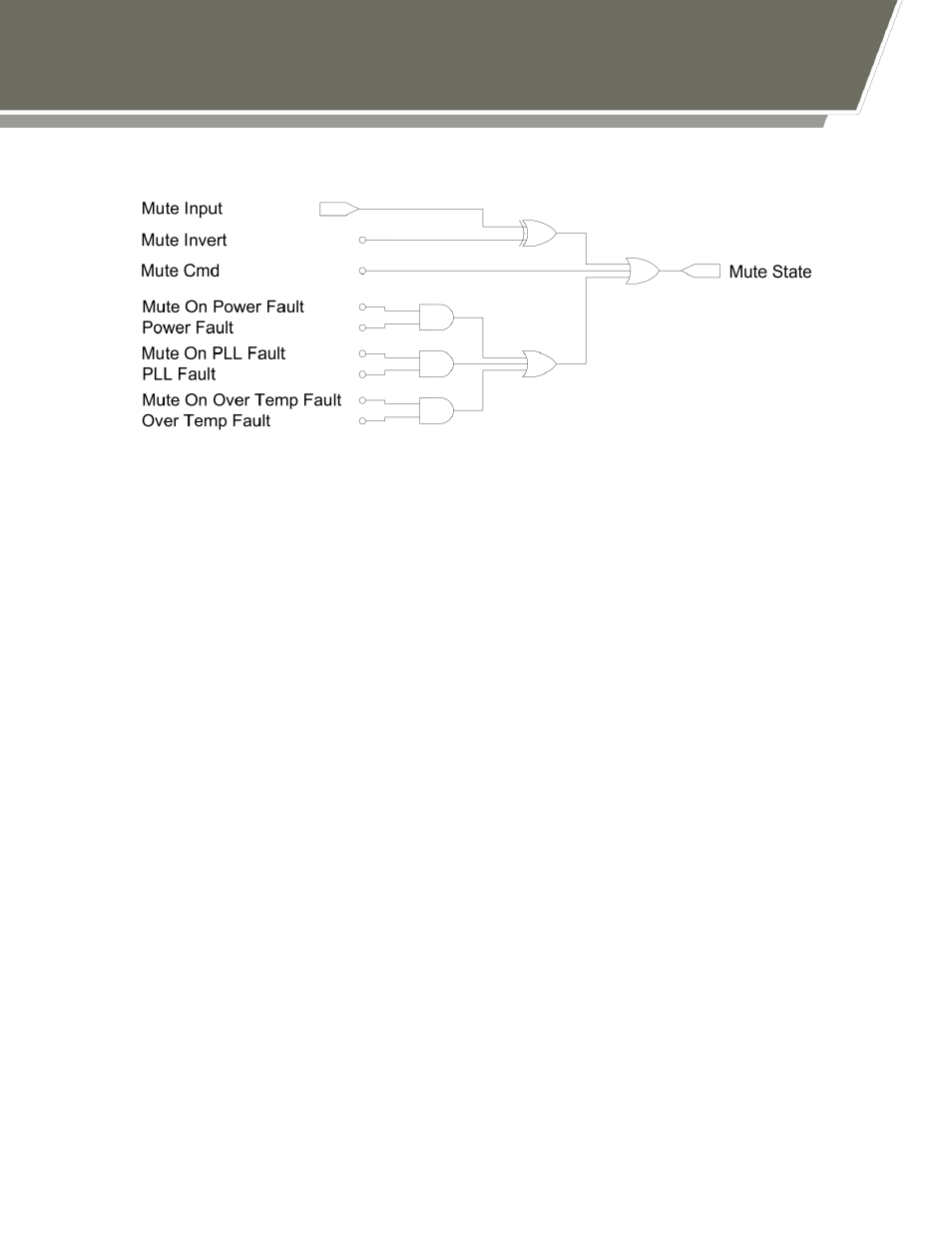
Figure 5: Revised Mute State Logic
Hardware-Based Muting
Hardware-based muting is controlled by three values: the Mute Input hardware line, the
Mute Invert software parameter, and the Mute Bias software parameter. The Mute Input
line allows external devices to control whether the ATOM Series BUC or SSPA is muted
or unmuted. The signal value required to mute or unmute the ATOM device is
determined by the value of the Mute Invert parameter. If Mute Invert is 0, then setting
Mute Input to 0V will unmute the device and setting Mute Input to 5V will mute the
device. If Mute Invert is 1, then setting Mute Input to 0V will mute the device and setting
Mute Input to 5V will unmute the device.
The Mute Bias signal controls the value of the Mute Input hardware line if the hardware
line is left floating. If Mute Bias is 0, then a floating Mute Input line will be pulled down to
0V. If Mute Bias is 1, then a floating Mute Input line will be pulled up to 5V.
Note that in the above logic diagrams, the Mute Input signal is assumed to already take
the Mute Bias into account.
By default, both Mute Bias and Mute Invert are set to 0.
The hardware-based muting parameter interactions are summarized in Table 4 below: