Installation & wiring, Stand-alone wiring, Condenser type selection – Orion System Two Condenser Head Pressure II Module User Manual
Page 5: Condenser signal b, Condenser signal a
Two Condenser Head Pressure II Module Technical Guide
INSTALLATION & WIRING
5
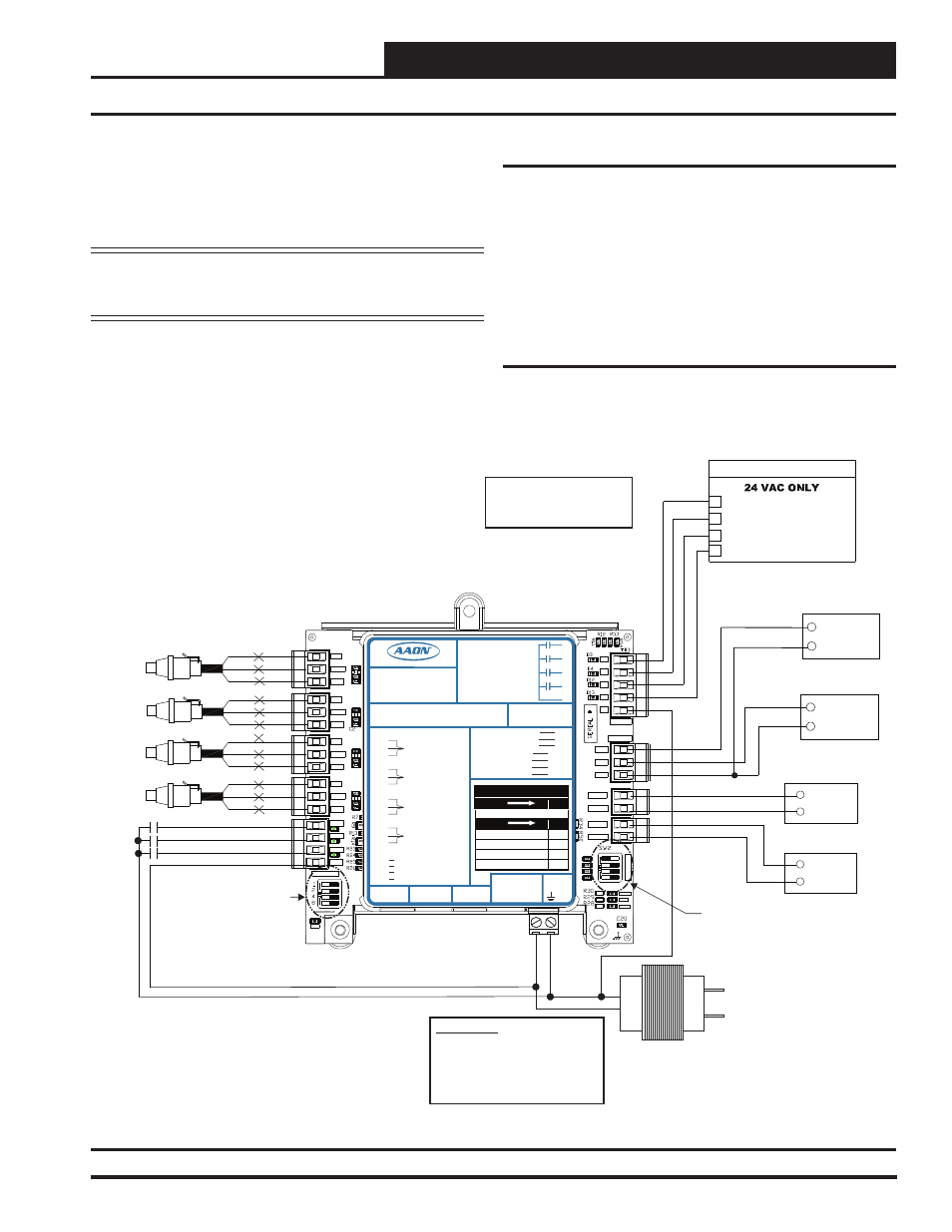
Figure 3: Two Condenser Head Pressure II Module Wiring Diagram (Stand-Alone)
Stand-Alone Wiring
SIG
GND
+V
BK
RD
WH
24 VAC Transformer
3 VA Minimum
Line Voltage
24 V
A
C
GND
WARNING!!
Observe Polarity! All boards
must be wired with GND-to-GND
and 24 VAC-to-24 VAC. Failure
to observe polarity could result in
damage to the boards.
OE370-23-HP2C2
Two Condenser Head Pressure II Module
+5V
SIG 2
GND
OP
T
IO
N
S
ALARM
ANALOG
STAT
+5V
COMM
GND
SIG 4
GND
R1
R2
GND
RELAYS
SIG 3
+5V
GND
+5V
SIG 1
R3
R4
Rc
AO1
AO2
PWM1-
PWM1+
PWM2-
PWM2+
SIG
GND
+V
BK
RD
WH
SIG
GND
+V
BK
RD
WH
SIG
GND
+V
BK
RD
WH
Head Pressure Transducers
0 - 667 PSI
(One Per Refrigerant Circuit)
PWR
OPTIONS Dip Switch is
Used for Setting the Head
Pressure Setpoint if Not
Using Default Setpoint.
COM
+
Condenser
Signal B
COM
+
Condenser
Signal A
CONDENSER A ENABLE
R1
HVAC UNIT CONNECTION
R3
CONDENSER B ENABLE
NOTE:
NORMALLY OPEN AND
RATED FOR 24 VAC POWER
ONLY
ALL RELAY OUTPUTS
ARE
- 1 AMP MAXIMUM LOAD
COMM
Set ADDRESS Dip Switch 1 to ON
for Water Cooled or to OFF for Air
Cooled. Currently showing OFF for
Air Cooled.
ADDRESS Dip Switch 2 is not used
in this application..
Set ADDRESS Dip Switch 3 to ON
to disable Circuit B alarms when
only one Condenser is Used.
Currently showing OFF.
Set ADDRESS Dip Switch 4 to OFF
to make reversing valve "ON to
Heat / OFF to Cool.” Set to ON to
make reversing valve “ON to Cool /
OFF to Heat.” Currently showing
OFF.
CONDENSER A ON/OFF
CONDENSER B ON/OFF
COM
ADDRESS
BIN 1
BIN 2
BIN 3
COM
REVERSING VALVE A/B ON/OFF
REVERSING VALVE B ENABLE
REVERSING VALVE A ENABLE
R4
R2
+24 Volts
Condenser Fan A
ECM Motor
Duty Cycle
Condenser Fan B
ECM Motor
YELLOW
BLUE +24 OUT
+24 Volts
Duty Cycle
YELLOW
BLUE +24 OUT
LED BLINK CODES
LED NAME
STAT
BLINKS QTY. OF SENSORS INSTALLED
LED NAME
ALARM
NO PROBLEMS
0
NO SENSORS DETECTED
1
HIGH HEAD PRESSURE DETECTED
2
LOW HEAD PRESSURE DETECTED
3
WattMaster Label
#LB102110-A
Rev.: 1A
E-BUS
Connector
E-BUS
Connector
+5V
SIG 1
GND
+5V
SIG 2
GND
+5V
SIG 3
GND
+5V
SIG 4
GND
+24
VAC
GND
BIN 1
BIN 2
BIN 3
COM
HEAD
PRESSURE
TRANSDUCER #1
HEAD
PRESSURE
TRANSDUCER #2
HEAD
PRESSURE
TRANSDUCER #3
HEAD
PRESSURE
TRANSDUCER #4
REV. VLV. ENABLE INPUT
COMMON
PWM2+
AAON No.:
V20660
AO1
AO2
GND
COND. A ENABLE INPUT
COND. B ENABLE INPUT
COND. A SIGNAL
COND. B SIGNAL
PWM1-
PWM1+
PWM2-
COND. FAN A
COND. FAN B
COND. FAN A
COND. FAN B
GND
Two Condenser Head Pressure II Module
2C2
Orion No.:OE370-23-HP
www.aaon.com
RELA
Y
C
ONT
A
CT
RA
TING
IS
1
A
MP
MAX
@
24
V
A
C
COND. A ENABLE
COND. B ENABLE
REV. VLV. A ENABLE
REV. VLV. B ENABLE
R1
R2
R3
R4
RC
RELAY COMMON
A1
A2
B1
B2
5. Check all wiring leads at the terminal block for tightness.
Be sure that wire strands do not stick out and touch adjacent
terminals. Confi rm that all transducers required for your
system are mounted in the appropriate location and wired into
the correct terminals.
WARNING: Be sure all controllers and modules are
powered down before connecting or
disconnecting HSSC cables.
Stand-Alone Wiring
To operate the Two Condenser Head Pressure II Module as Stand Alone,
connect the Module to a 24 VAC connection with an appropriate VA
rating. See Figure 3 for wiring.
Check all wiring leads at the terminal block for tightness. Be sure that
wire strands do not stick out and touch adjacent terminals. Confi rm that
all transducers required for your system are mounted in the appropriate
location and wired into the correct terminals.
Condenser Type Selection
As shown in Figure 3, set ADDRESS Dip Switch 1 to ON for water
cooled or to OFF for air cooled. Refer to page 8 for further instructions.