Water source heat pump module, Installation & wiring, Technical guide – Orion System Water Source Heat Pump Module User Manual
Page 5: Power supply, Environmental requirements, Mounting, Figure 2: water source heat pump module dimensions
Technical Guide
Water Source Heat Pump Module
5
Installation & Wiring
Power Supply
The Water Source Heat Pump Module requires a 24 VAC power con-
nection with an appropriate VA rating.
If you will be connecting the Water Source Heat Pump Module to the
VCM-X WSHP Controller, one of the most important checks to make
before powering up the system for the fi rst time is to make sure that the
VCM-X WSHP Controller is confi gured properly for your application.
Refer to the VCM-X Controller Technical Guide for more information.
WARNING: Observe polarity! All boards must be wired
GND-to-GND and 24 VAC-to-VAC. Failure to
observe polarity could result in damage to the
boards.
Environmental Requirements
The Water Source Heat Pump Module needs to be installed in an environ-
ment that can maintain a temperature range between -30°F and 150°F
and not exceed 90% RH levels (non-condensing).
Mounting
The Water Source Heat Pump Module is housed in a plastic enclosure. It
is designed to be mounted by using the 3 mounting holes in the enclosure
base. It is important to mount the module in a location that is free from
extreme high or low temperatures, moisture, dust, and dirt. Be careful
not to damage the electronic components when mounting the module.
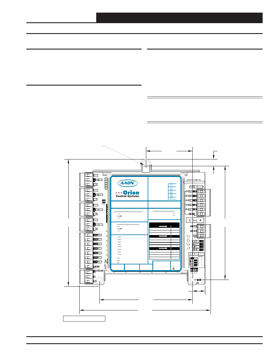
See Figure 2 for Module dimensions (dimensions are in inches).
Figure 2: Water Source Heat Pump Module Dimensions
WATTMASTER CONTROLS
5.64
5.83
2.07
4.14
5.05
0.29
0.56
0.18 DIA. TYP. 3 PL.
Note: Height is 1.49 inches.
WattMaster Label
#LB102069-B
Rev.: 1E
E-BUS
Connector
E-BUS
Connector
+24
VAC
GND
WSHP Module
Orion No.: OE334-23-WPM-C
AAON Coil No.: 30318
www.aaon.com
www.orioncontrols.com
RELAY CONTACT RATING
IS 1 AMP MAX @ 24 VAC
COMP. A2 ENABLE
COMP. A1 ENABLE
R1
R2
R3
R4
R5
RC
RELAY COMMON
COMP. B1 ENABLE
COMP. B2 ENABLE
ALARM OUTPUT
+5V
PRES
GND
+5V
PRES
GND
BIN 1
BIN 2
BIN 3
BIN 4
BIN 5
BIN 6
BIN 7
COM
SUCT. PR. SENSOR
PRES 1=A1, PRES 2=N/A
PRES 3=B1, PRES 4=N/A
NOT USED
PRES 1=A1, PRES 2=N/A
PRES 3=B1, PRES 4=N/A
COMP. A1 ENABLE
COMP. A2 ENABLE
COMP. B1 ENABLE
COMP. B2 ENABLE
COOL ENABLE
WATER POF
NOT USED
COMMON
T 1
T 2
GND
LEAVING WATER TEMP
GROUND
NOT USED
LED BLINK CODES
LED NAME
STATUS
OFF MODE
1
COOLING MODE
2
HEATING MODE
3
LED NAME
ALARM
LOW SUCTION PRESSURE
1
COMPRESSOR LOCKOUT
2
WATER FLOW FAILURE
3
LOW LEAVING WATER TEMP.
4
LED NAME
PRES 1-4
SENSOR DETECTED
ON
NO SENSOR DETECTED
OFF
LOW SUCTION PRESSURE
1
COMPRESSOR LOCKOUT
2
AO1
A2O
CIRCUIT A -COMP. A1
+5 NOT USED, PRES TO P6 & GND TO P5
+5 TO RED, PRES TO WHT & GND TO BLK
CONNECT TO CNTLR C2 TERM.
CIRCUIT B - COMP. B1
DIGITAL COMRESSORS
DIGITAL COMP. A1 & B1
NON-DIGITAL COMPRESSORS