Water source heat pump module, Installation & wiring, Technical guide 6 important wiring considerations – Orion System Water Source Heat Pump Module User Manual
Page 6: Stand-alone wiring
Water Source Heat Pump Module
Technical Guide
6
Important Wiring Considerations
Please read carefully and apply the following information when wiring
the Water Source Heat Pump Module:
1. To operate the Water Source Heat Pump Module in Stand-
Alone mode, you must connect power to the 24 VAC input
terminal block. Do not allow wire strands to stick out and
touch adjoining terminals. This could potentially cause a short
circuit.
2. The 1 to 5 VDC signals for the Compressor modulation need
to use 18-gauge shielded twisted pair cable, and the Drain wire
must be the GND signal.
3. All 24 VAC wiring must be connected so that all ground
wires remain common. Failure to follow this procedure can
result in damage to the module and connected devices.
Installation & Wiring
4. Be sure all modular wiring harness connectors are seated
fi rmly in their respective modular connectors on the circuit
board.
5. All wiring is to be in accordance with local and
national electrical codes and specifi cations.
6.
Check all wiring leads at the terminal block for tightness.
Be sure that wire strands do not stick out and touch adjacent
terminals. Confi rm that all transducers required for your
system are mounted in the appropriate location and wired into
the correct terminals.
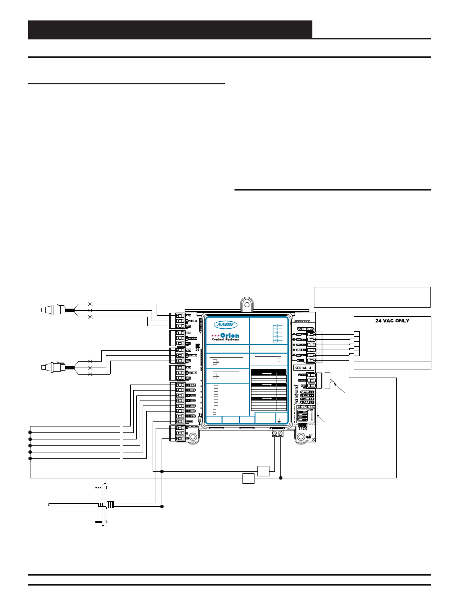
Stand-Alone Wiring
To operate the Water Source Heat Pump Module as Stand Alone, con-
nect the Module to a 24 VAC power connection with an appropriate VA
rating. See Figure 3 for wiring.
Figure 3: Water Source Heat Pump Module as Stand-Alone
NOTE:
NORMALLY
OPEN AND RATED FOR 24 VAC POWER ONLY
ALL RELAY OUTPUTS ARE
COMPRESSOR A2 ENABLE OUTPUT
COMPRESSOR A1 ENABLE OUTPUT
GND
T1
BIN1
R
E
R1
R4
R5
R3
R2
COMM
CIRCUIT A
SUCTION PRESSURE TRANSDUCER
BK
RD
WH
WATER POF CONTACT
COMPRESSOR A1 ENABLE CONTACT
BK
RD
WH
WATTMASTER CONTROLS
COMPRESSOR B1 ENABLE OUTPUT
COMPRESSOR B2 ENABLE OUTPUT
ALARM OUTPUT
COMPRESSOR B1 ENABLE CONTACT
COOL ENABLE CONTACT
BIN3
BIN5
BIN6
COM
LEAVING WATER TEMPERATURE
NOTE:
OUTPUTS ARE NOT USED ON
STAND ALONE APPLICATIONS
DIP SWITCH
NOT USED FOR
STAND ALONE
APPLICATION
HVAC UNIT CONNECTIONS
CIRCUIT B
SUCTION PRESSURE TRANSDUCER
GND
24 V
A
C
- 1 AMP MAXIMUM LOAD
OE334-23-WPM-C
Water Source Heat Pump
Module
BIN2
COMPRESSOR A2 ENABLE CONTACT
BIN4
COMPRESSOR B2 ENABLE CONTACT
WattMaster Label
#LB102069-B
Rev.: 1E
E-BUS
Connector
E-BUS
Connector
+24
VAC
GND
WSHP Module
Orion No.: OE334-23-WPM-C
AAON Coil No.: 30318
www.aaon.com
www.orioncontrols.com
RELAY CONTACT RATING
IS 1 AMP MAX @ 24 VAC
COMP. A2 ENABLE
COMP. A1 ENABLE
R1
R2
R3
R4
R5
RC
RELAY COMMON
COMP. B1 ENABLE
COMP. B2 ENABLE
ALARM OUTPUT
+5V
PRES
GND
+5V
PRES
GND
BIN 1
BIN 2
BIN 3
BIN 4
BIN 5
BIN 6
BIN 7
COM
SUCT. PR. SENSOR
PRES 1=A1, PRES 2=N/A
PRES 3=B1, PRES 4=N/A
NOT USED
PRES 1=A1, PRES 2=N/A
PRES 3=B1, PRES 4=N/A
COMP. A1 ENABLE
COMP. A2 ENABLE
COMP. B1 ENABLE
COMP. B2 ENABLE
COOL ENABLE
WATER POF
NOT USED
COMMON
T 1
T 2
GND
LEAVING WATER TEMP
GROUND
NOT USED
LED BLINK CODES
LED NAME
STATUS
OFF MODE
1
COOLING MODE
2
HEATING MODE
3
LED NAME
ALARM
LOW SUCTION PRESSURE
1
COMPRESSOR LOCKOUT
2
WATER FLOW FAILURE
3
LOW LEAVING WATER TEMP.
4
LED NAME
PRES 1-4
SENSOR DETECTED
ON
NO SENSOR DETECTED
OFF
LOW SUCTION PRESSURE
1
COMPRESSOR LOCKOUT
2
AO1
A2O
CIRCUIT A -COMP. A1
+5 NOT USED, PRES TO P6 & GND TO P5
+5 TO RED, PRES TO WHT & GND TO BLK
CONNECT TO CNTLR C2 TERM.
CIRCUIT B - COMP. B1
DIGITAL COMRESSORS
DIGITAL COMP. A1 & B1
NON-DIGITAL COMPRESSORS