Installation & wiring, Supply fan vfd signal – Orion System SA Controller User Manual
Page 18
Zone
Zone
Installation & Wiring
SA Controller Technical Guide
18
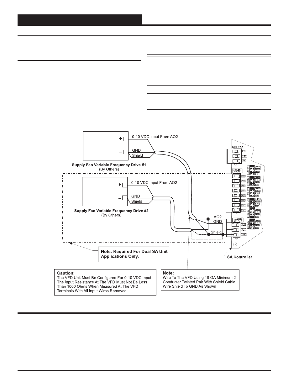
Supply Fan VFD Signal or Zoning
Bypass Damper Actuator Signal
The Supply Fan VFD or Zoning Bypass Damper Actuator Signal is a
0-10 VDC output from AO2 on the SA Controller. This signal output can
be connected to the Supply Fan Variable Frequency Drive to modulate
the Supply Fan speed and control Duct Static Pressure utilizing the Duct
Static Pressure Sensor connected to the SA Controller. Alternatively, it
can be connected to a Zoning Bypass Damper Actuator that will modu-
late the Zoning Bypass Damper Actuator to control Duct Static Pressure
utilizing the Duct Static Pressure Sensor connected to the SA Controller.
A Duct Static Pressure Sensor must be connected in order for the VFD
or Zoning Bypass Damper Actuator to operate. See Figures 14 and 15
for detailed wiring.
Supply Fan VFD Signal
Caution: Variable Frequency Drive units can cause large transient
noise spikes which can cause interference to be propagated on other
electronic equipment. Use shielded wire wherever possible and route
all sensor and controller wiring away from the Variable Frequency
Drive and the HVAC Unit electrical wiring.
NOTE: For Dual Cabinet Units, VFD #2 must be wired in
parallel to VFD #1 as shown in Figure 14 below.
Figure 14: Supply Fan VFD Wiring