Troubleshooting, Led diagnostics – Orion System SA Controller User Manual
Page 52
Zone
Zone
Troubleshooting
SA Controller Technical Guide
52
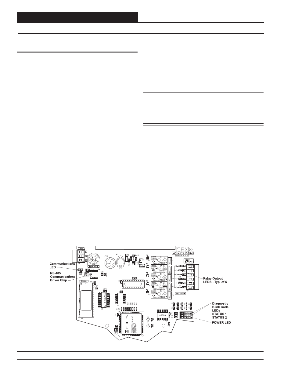
Using LEDs To Verify Operation
The SA Controller is equipped with 4 LEDs that can be used as very
powerful troubleshooting tools. See Figure 30 below for the LED loca-
tions. The LEDs and their uses are as follows:
REC
- This LED will light up to indicate system communications.
POWER
- This LED will light up to indicate that 24 VAC power has
been applied to the controller.
STATUS 1
- This is the diagnostic blink code LED. It will light up
and blink out diagnostic codes. STATUS 1 LED also represents the tens
column in the address blink code.
STATUS 2
- This is the diagnostic blink code LED. It will light up and
blink out diagnostic codes. STATUS 2 LED also represents the ones
column in the address blink code.
POWER LED Operations
When the SA Controller is powered up, the POWER LED should light
up and stay on continuously. If it does not light up, check to be sure that
you have 24 VAC connected to the controller, that the wiring connections
are tight, and that they are wired for the correct polarity. The 24 VAC
power must be connected so that all ground wires remain common. If
after making all these checks, the POWER LED does not light up, please
contact WattMaster Controls Technical Support for assistance.
REC LED Operations
When power is applied to the controller, the REC LED will also light
up. If this is a Stand Alone System (one controller only on the loop) or
an Interconnected System (several SA Controllers tied together without
a CommLink), the REC LED will glow continuously. The REC LED
will fl icker when you are connected to the SA Controller and you are
entering setpoints with the Modular Service Tool or one of the System
Managers. It will also fl icker if this is a Networked System. If this is a
Networked System (the system has a CommLink installed), the REC
LED should fl icker rapidly, indicating that the system is communicat-
ing. A “fl icker” is defi ned as a brief moment when the LED turns off
and then back on. It may be easier to see this “fl icker” if you cup your
hand around the LED.
If the REC LED does not operate as indicated above, fi rst check the
address switch setting. Verify the address switch as outlined in the Di-
agnostic LEDs Operations section on page 53. See Figure 29 on page
34 for complete address switch setting instructions.
NOTE: STATUS 1 LED represents the tens position and STATUS
2 LED represents the ones position of the controller address. If the
address of the controller is set to 59 with the address switch, fi rst
STATUS 1 LED will blink 5 times, and then STATUS 2 LED will
blink 9 times.
If the address switch setting is correct and the REC LED still does not
behave as indicated above, check to be sure the operator’s interface is
connected correctly. If you are using the Modular Service Tool, verify
that it is plugged in securely to the DIN connection on the SA Controller.
If you are using one of the System Manager Operator’s Interfaces, see
the SA Controller Operator Interfaces Technical Guide or the System
Manager TS Operator Interfaces Technical Guide for a connection
diagram.
If the REC LED still does not behave correctly, check the voltages at
the communications terminal block. Be sure the Controller is powered
up for this test. Unplug the communications terminal block from the
controller and check the DC voltage between T and SHLD and between
R and SHLD. Check the voltage with a digital multimeter set to DC
volts. The voltage should be between 3.0 to 3.2 VDC between SHLD
and either T or R. If the voltage is not in this range, you probably have
a damaged driver chip that must be replaced.
For driver chip replacement instructions, please see the Orion Controls
SA Controller Component & System Wiring Technical Guide for more
information or contact the factory for further assistance.
LED Diagnostics
Figure 31: SA Controller Diagnostic LED Locations