Installation & wiring, Modulating cooling device wiring – Orion System SA Controller User Manual
Page 27
SA Controller Technical Guide
Installation & Wiring
27
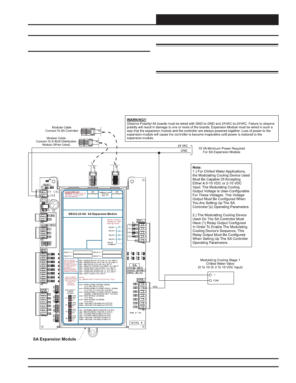
Chilled Water Valve
For Chilled Water Applications, the Modulating Cooling Signal(s) can
be confi gured for either a 0-10 VDC or 2-10 VDC output signal when
programming the controller. The output signal can also be confi gured
for either Direct Acting or Reverse Acting operation as required by your
application. This signal output would be connected to a Modulating
Chilled Water Valve.
See Figure 23 below for detailed wiring of a Chilled Water Valve.
Warning: It is very important to be certain that all wiring is
correct as shown in the wiring diagram below. Failure to observe the
correct polarity could result in damage to the Modulating Cooling
Device or the SA Expansion Module.
Figure 23: Chilled Water Valve Wiring
Modulating Cooling Device Wiring