Installation & wiring, Relay expansion module overview and wiring – Orion System SA Controller User Manual
Page 30
Zone
Zone
Installation & Wiring
SA Controller Technical Guide
30
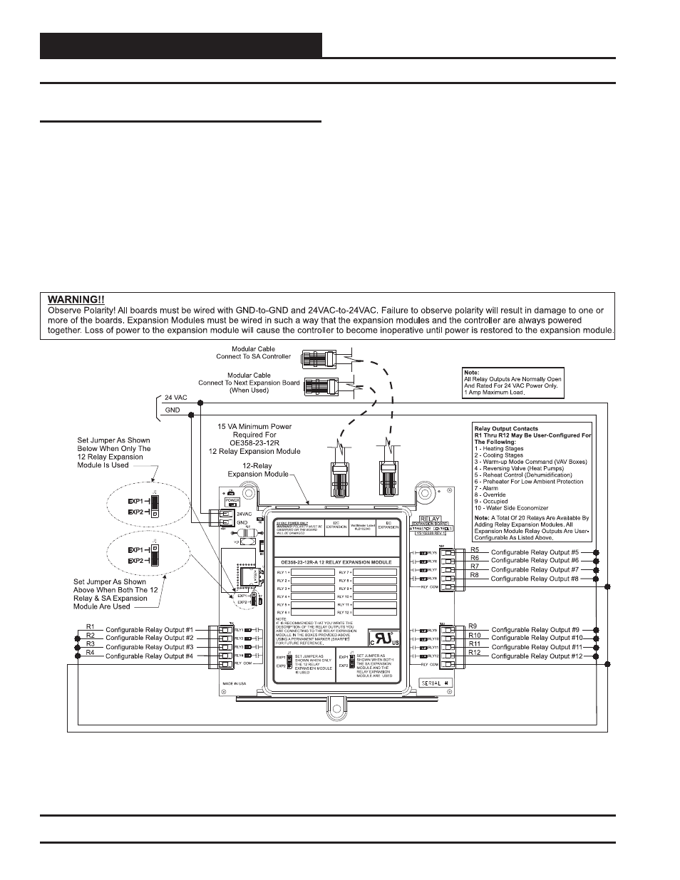
12-Relay Expansion Module Overview and Wiring
Figure 25: OE358-23-12R – 12-Relay Expansion Module Wiring and Jumper Settings
12-Relay Expansion Module
Two different Expansion Modules are available for use with the SA
Controller to provide additional inputs and outputs beyond those found
on the SA Controller.
The SA Expansion Module ( OE333-23-SA) is provided with 8 Binary
Inputs, 4 Analog Inputs, 4 Relay Outputs, and 5 Analog Outputs. See
Figures 16 and 17 on page 20 and 21 for complete wiring details.
The 12-Relay Expansion Module ( OE358-23-12R) provides for 12 Dry
Contact Confi gurable Relay Outputs. See Figure 25 below for complete
wiring details.
The expansion modules can be used individually or together to provide
the required inputs and outputs for your specifi c applications.
When using the 12-Relay Expansion Module, you must correctly confi g-
ure a set of jumpers on the board depending on whether it will be used
by itself or in addition to the SA Expansion Module.
The jumpers are located on the edge of the 12-Relay Expansion Module
on the same side of the module as the power connection. See Figure
25 below for details regarding setting the switch correctly for your
application.