Fiber and video ports, Transmitter receiver – Thinklogical Velocitykvm-4, 5, 8, 24, 28, 34, 35 & 38 Manual User Manual
Page 20
V e l o c i t y K V M E x t e n d e r P r o d u c t M a n u a l , R e v . B , J a n u a r y , 2 0 1 4
Page 20
VelocityKVM Transmitters and Receivers with the FireWire Option
:
Peripheral and Update Ports, LED Indicators
Audio OUT (speakers)
Audio IN (microphone)
Stereo Emitter OUT (3D)
Audio IN (source)
Audio OUT
(from microphone)
Stereo Emitter IN (3D)
RS-232
Update Ports
RS-232
PS2 Keyboard/Mouse (source)
Local Keyboard/Mouse (HID or PS2)
USB HID, PS2 and USB 2.0
FireWire Indicator LEDs
PWR:
FireWire PCB power On/Off
CP:
ON=Cable Powered
CLINK:
ON=CPU connected (linked)
FOL:
(Fiber Optic Link) ON=connection, BLINKING=no connection
Unmarked LEDs are non-functioning
NOTE: The FireWire option requires 2 additional Fiber Optic Cables.
FireWire Indicator LEDs
PWR:
FireWire PCB power On/Off
CP:
ON=Cable Powered
CLINK:
ON=CPU connected (linked)
FOL:
(Fiber Optic Link) ON=connection, BLINKING=no connection
Unmarked LEDs are non-functioning
FireWire (Fibers & IN Port)
FireWire (Fibers & OUT Port)
Transmitter
Receiver
USB HID & USB 2.0 IN
VEL-F00M04-LCTX
VEL-F00M04-LCRX
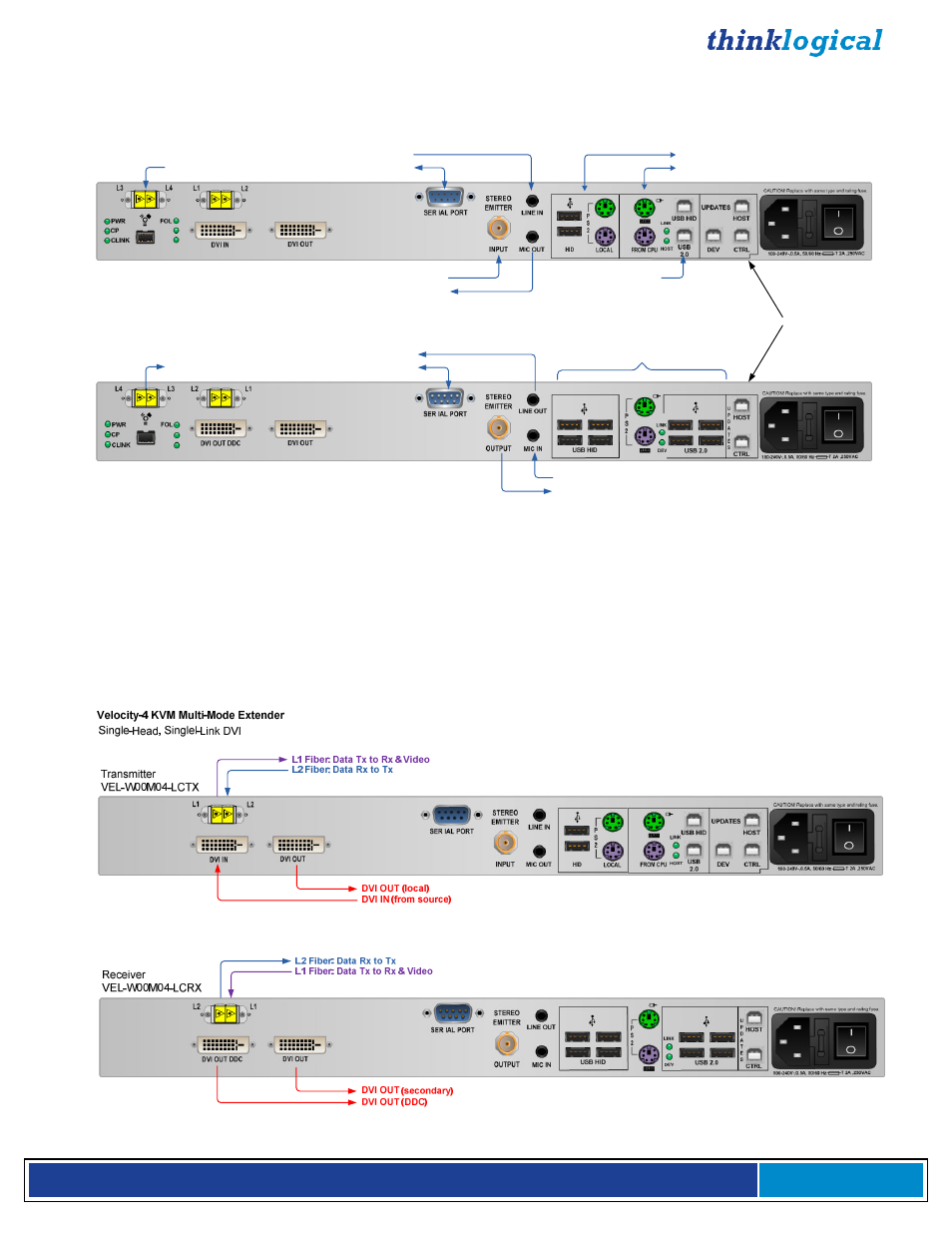
Fiber and Video Ports
The following transmitter and receiver rear panel diagrams explain the functions of the fiber optic cable
input and output ports and the video input and output ports for each of the VelocityKVM Extenders. For
the fiber connections,
Optical Fiber
L1, which carries both DATA from Tx to Rx and VIDEO, is in
purple,
Optical Fiber L2, which carries DATA from Rx to Tx, is in blue
and
all VIDEO ONLY fibers
are in red.
Refer to the Quick Start Guides in Appendix B (pg. 45-52) for more information.