Velocitykvm-5 velocity kvm-5, Quick start guide – Thinklogical Velocitykvm-4, 5, 8, 24, 28, 34, 35 & 38 Manual User Manual
Page 46
V
e
l
o
c
i
t
y
K
V
M
E
x
t
e
n
d
e
r
P
r
o
d
u
c
t
M
a
n
u
a
l
,
R
e
v
.
B
,
J
a
n
u
a
r
y
,
2
0
1
4
P
a
g
e
4
6
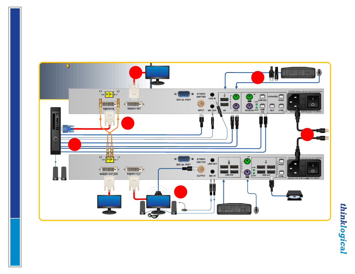
QUICK START GUIDE
STEP 5:
If desired, connect your optional
local keyboard & mouse by inserting the PS/2
or USB HID connectors into the VelocityKVM
Transmitter’s local devices receptacles and
connect the optional local RGB/DVI display to
the Transmitter’s RGB/DVI OUT Port. Ensure
all system functions are operating properly.
USB HID or PS2
Keyboard/Mouse
QUICK START GUIDE
Velocitykvm-5
Velocity
kvm-5
Multi-Mode Fiber Extension System – Single Head, Single Link RGB/DVI
Multi-Mode Fiber Extension System – Single Head, Single Link RGB/DVI
1
4
5
5
Local RGB/DVI
OUT
Audio OUT ►
RGB/DVI IN
STEP 1:
Connect your Multi-Mode Fiber
Optic Cables between the Transmitter and
Receiver units (up to 1000 meters) as shown.
L1: Data Tx to Rx and Video
L2: Data Rx to Tx
◄Audio IN
PS/2 Keyboard
PS/2 Mouse
USB HID (Kybd/Mouse)
USB 2.0
Stereo Emitter IN
STEP 2:
Ensure that
the POWER ON/OFF
switch is in the OFF
position (0) on both
the Tx and Rx units.
Connect the supplied
AC Power Cords to
both units and plug
each into a standard
AC supply. Turn both
switches ON (1).
2
VELOCITY-5W_Manual_QSG_Rev_A
Source CPU
USB HID or PS2
Keyboard/Mouse
3
USB 2.0
Audio IN/OUT
Stereo 3-D
RGB/DVI OUT
STEP 3:
Connect the destination RGB/DVI and KVM
devices to the VelocityKVM Receiver using RGB/
DVI cables and standard copper cables. Ensure the
devices are turned ON.
RGB/DVI OUT
DDC
Local
Audio
OUT
A
.B
.2
V
e
lo
c
ity
K
V
M
-5
Q
u
ic
k
S
ta
rt
G
u
id
e