Vantage Point E3S User Manual
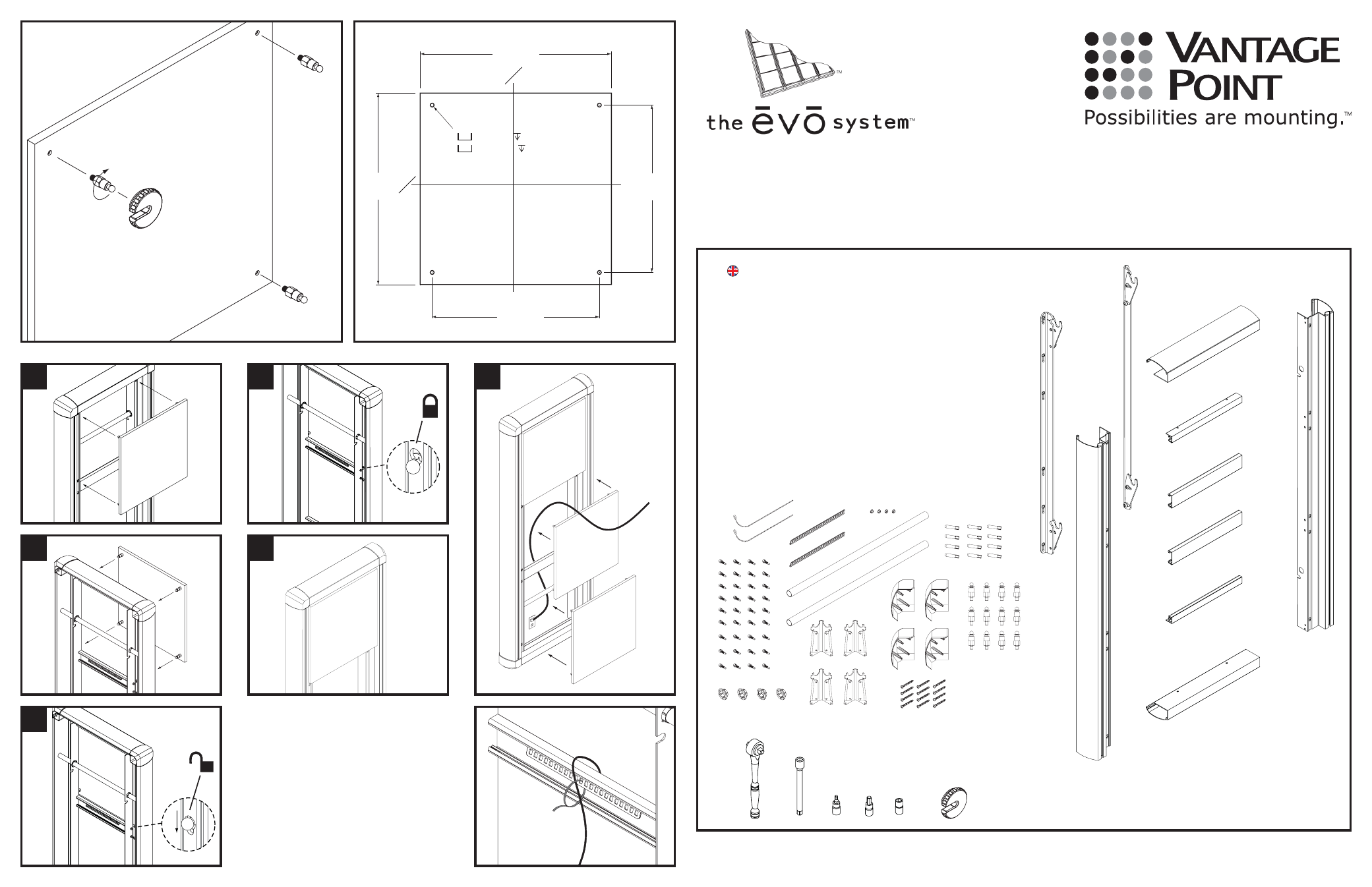
3 high single frame kit assembly instructions, Cl c l
L
M
N
O
P
P
O
N
R
Q
Vantage Point Products Corp • P.O. Box 2485 Santa Fe Springs, CA 90670 USA Tel: 1.800.582.9595
• Canada Tel: 905.607.9994 • Europe Tel: 31.72.581.6056 • Web Site: www.vanptc.com • Email: [email protected]
15.875
40.32 cm
13.875
35.24 cm
15.875
40.32 cm
13.875
35.24 cm
Ø 0.1875
Ø 0.47 cm
x
v
0.375
0.952 cm
v
x
C
L
C
L
S
T
U
V
W
X
A Wire
tie
2
B
5mm hex head screw
36
C Grommet
4
D Wire
tie
mount
2
E
Base support bar
2
F Corner
Bracket
4
G Serrated
5mm
fl ange nut
4
H Corner
cover
4
I
3/8” dia. concrete wall anchor
12
J Panel
spacer
12
K
#14-2 1/2” phillips pan head s/m/s
12
L
L.H. wall bracket
1
M
R.H. wall bracket
1
N
Upper / lower extrusion
2
O Upper
/
lower
fi ll
2
P Cross
support
2
Q
L.H. vertical extrusion
1
R
R.H. vertical extrusion
1
S
1/4” drive ratchet
1
T
4” long 1/4” drive extension
1
U
4mm hex 1/4” drive
1
V
6mm hex 1/4” drive
1
W
7mm socket 1/4” drive 6 point
1
X
Evo panel tool
ITEM
DESCRIPTION
QTY
B
C
D
E
F
G
H
I
J
K
A
3 High Single Frame Kit Assembly
Instructions
1
2
3
4
5
6
A
Ei01-12/06
MAX WEIGHT LOAD: 500 lbs
226.79 kg
NOTE: Each wall bracket holds a max weight load of 250 lbs. (113.39 kg)
J
J
J
PANEL
(NOT INCLUDED)
X
E3S