Dsu mp configuration, Port – Verilink PRISM 3060-10 (34-00252.4) Product Manual User Manual
Page 30
22
O
PERATION
DSU MP
Configuration
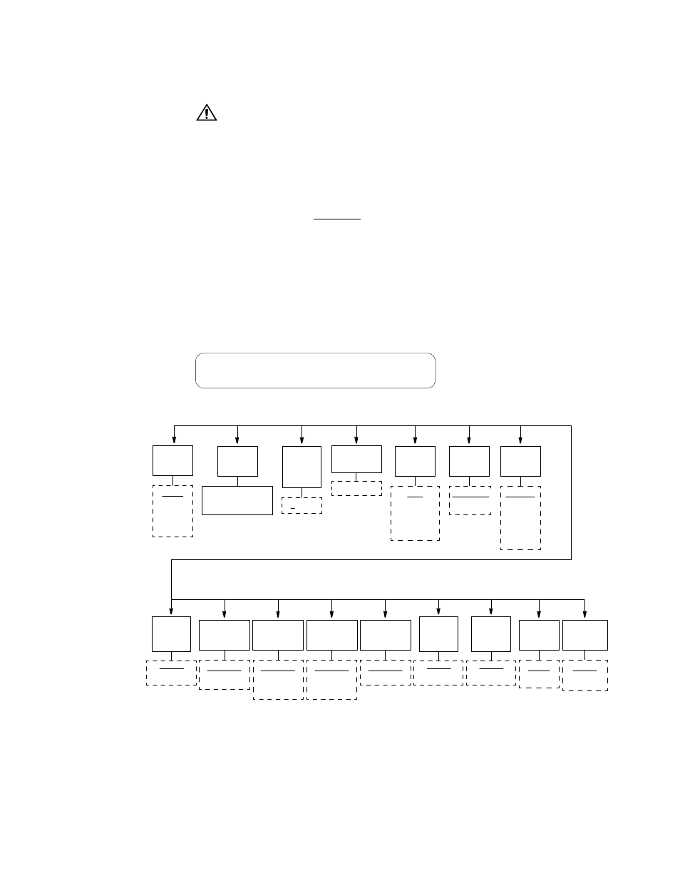
The DTE Port Configuration display (Figure 3-9) allows configuration parameters
to be set for the DSU MP ports.
It is very important that the DTE ports at opposite ends of a link be configured
identically. For example, if port A of one DSU MP is configured for 19.2 kbps async,
then port A at the far end must also be configured for 19.2 kbps async. Neglecting to do
this may not only result in the inability to pass DTE traffic from end to end, but also
misdirect data intended for one port (ex. A) to the opposite port (ex. B) at the far end. This
data swapping is a side effect of the rate-swapping feature and only occurs at DTE rates of
31.2 kbps (in TXP-I mode) and 38.4 kbps (in TXP-II mode) when units are configured
improperly.
Defaults are shown underlined.
Port #
This parameter allows selecting the configuration of the slot (3, 4, 5, or 6 for the
3060 -10) and the port: 1A through 6A in DDS mode and TXP mode with TDM
turned off; 1A, 1B, 2A, 2B, 3A, 3B, 4A, 4B, 5A, 5B, 6A, and 6B in the TDM
modes.
The following parameters are for the displayed slot, DSU, and port.
✍
≤
DDS Rate
Port
Rate
Port
Type
RS-232C
V.35 (Port
A only)
EIA-530
(Port A
only)
Internal
External
CTS
Control
Force True
Internal
V.54
Loop
Enable
Disable
Alarm on
DTR Loss
Disable
Enable
DSR
Control
Force True
Force False
Internal
DCD
Control
Force True
Internal
Far RTS
Port
Transmit
Clock
Port
Format
Sync
Async (only
used in one
of the TXP
modes)
Starting
Channel
0 to 24
Number
DDS
Rate
DDS I, TXP I = 56K
DDS II, TXPII= 64K
Port
Mode
NON-TDM
TDM
Figure 3-9 First DSU MP Configuration Screen and Menu Diagram
DTE Port Configuration
Slot 5Port 1A Config Menu
Disable
Enable
LL
Control
Lead
Disable
Enable
RL
Control
Lead
RTS
Control
Force True
External
DDS
Mode
DDS-I
DDS-II
TXP-I
TXP-II