Nms in and nms out, Nms split cable, Nms in only – Verilink PRISM 4051 (34-00253.2) Product Manual User Manual
Page 17: Chassis operation
Network Management Connections 11
NMS IN and NMS OUT ports. The different connection methods are described in
the following paragraphs.
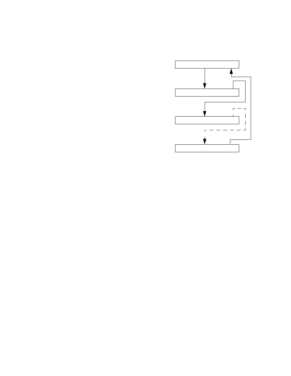
NMS IN and NMS OUT
The two 6-pin modular
connectors labeled NMS
IN and NMS OUT on
the 1051 rear panel may
be used for connection
to the 8100A Site
Controller. These ports
allow the connection of
multiple collocated units
in a daisychained
IN/OUT bus
arrangement as shown in
Figure 2-6. The OUT
port of one element is
connected to the IN port
of the next element, and
so on, to form a
complete chain among
the group of elements.
All units on the same NMS chain must use the same NMS bit rate.
NMS Split Cable
The 8100A Site Controller may be connected directly into the NMS chain between
two elements if connection to the supervisory port is not desired. A Y-cable is used
from the 8100A serial port which splits the transmit and receive signals into two
6-pin modular connectors for the NMS IN and NMS OUT ports. Ordering
information for this cable is found in Ordering Numbers on page 4.
NMS IN Only
The NMS IN connector provides both the transmit and receive signal pair. This
port may be used for a modem connection or as a VT100 terminal interface (refer
to Terminal Interface on page 21).
Chassis Operation
8100A Site Controller operation in the 1051 chassis has the units chained together.
The front panel supervisory port and the rear panel NMS ports operate in the same
fashion.
Figure 2-6 NMS Daisychain Arrangement
NMS OUT
8100A
NMS IN
Element
NMS IN
Element
NMS IN
Last
Element
✍