Vinpower Digital USBShark User Manual
Page 6
Advertising
3
Chapter 2: Getting to know the system
System Overview
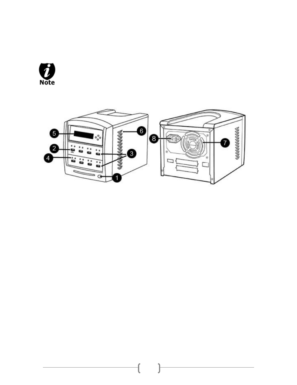
The image below is a representation of the flash duplicator casing. The design of
the casing may vary but the unit continue to operate using similar principles.
Figure 1-1 System Controls and Display
The components shown in Figure 1-1 are:
1. System Power On/Off Button
2. Source Flash Device Port (ex. USB, SD, CF, etc)
3. Target Flash Device Port (ex. USB, SD, CF, etc)
4. Flash Device Port Status Indicator
5. LCD Display & Operation Panel
6. System Ventilation Vents
7. Power Supply Fan
8. Power Cord Input
Advertising
This manual is related to the following products: