Verify power is connected – Wavetronix Click 201 (1 amp AC to DC converter) (CLK-201) - Quick-reference Guide User Manual
Page 3
5
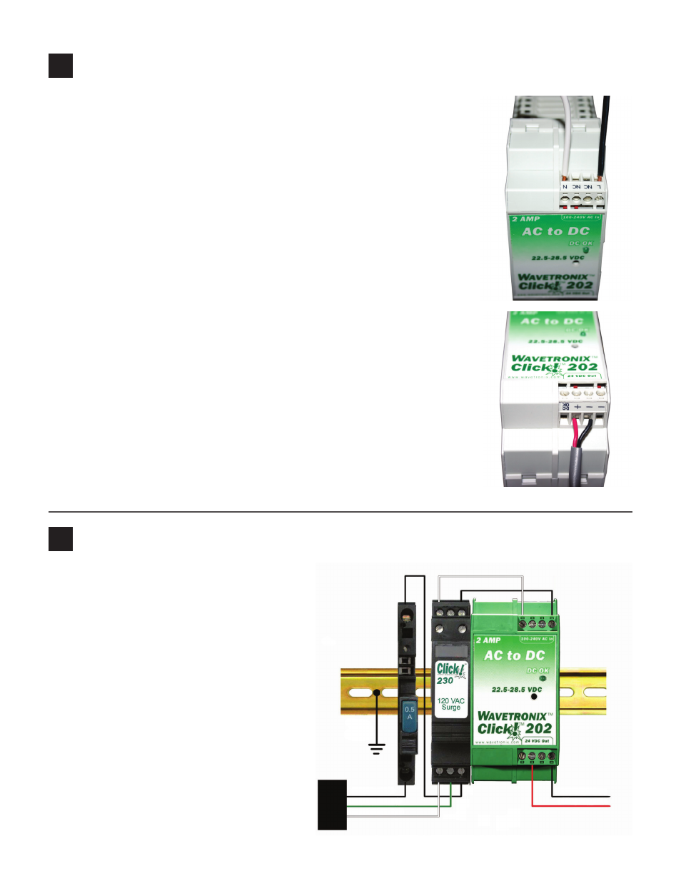
Wire the Click 201/202/204 AC to DC converter
Wiring AC power in
Follow the steps below to properly wire an AC to DC power conversion
module:
1 Mount the Click 201/202/204 onto the DIN rail.
2 Connect the line (hot) wire from the Click 230 into the L screw terminal
on the top of the Click 201/202/204. The line wire is usually black.
3 Connect the neutral wire from the Click 230 to the N screw terminal to
the top of the Click 201/202/204. The neutral wire is usually white.
Wiring DC power out
To power the sensor, 10–30 VDC needs to be connected to the Click 200 in
the pole-mount cabinet. Additionally, if there is a main traffic cabinet con-
nected by a homerun cable, you will need to connect DC power to the Click
200 in that cabinet.
1 Connect a +DC conductor (usually a red wire) to the + screw terminal
on the bottom of the Click 201/202/204.
2 Connect a -DC conductor (usually a black wire) to either of the - screw
terminals on the bottom of the Click 201/202/204.
Note. Do NOT connect to the DC OK screw terminal.
Some installations use a Click 203 instead of a Click 201/202/204. The Click
203 is covered in Part 7 of this document.
6
Verify power is connected
Once the power plant is attached to the DIN
rail and wired correctly, follow the steps below
to verify your connections:
1 Push the blue switch down on the front of
the Click 210 circuit breaker.
2 Make sure that the Click 201/202/204 DC
OK light is on.
Black (Line)
Green (Ground)
White (Neutral)
Red (+24 VDC)
Black (Ground)
Earth Ground