Connections gdw-11 – Westermo GDW-11 User Manual
Page 17
Advertising
17
6615-2203
PW
R
NE
T RD TD
1 2
5
4 3
2 1
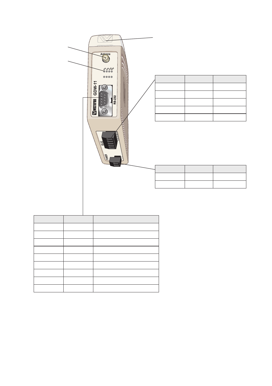
SIM interface under lid
Antenna interface
LED Indicators
(for details
see page 19)
Connections GDW-11
RS-232 screw terminal
5-position
Direction Description
No. 1
In
TD
No. 2
Out
RD
No. 3
In
DTR
No. 4
Out
DSR
No. 5
–
SG
Power connection
screw terminal
2-position
Direction Description
No. 1
In
– VDC
No. 2
In
+ VDC
RS-232 D-sub
9-position
Direction Description
No. 1
Out
Data Carrier Detect (DCD)
No. 2
Out
Receive Data (RD)
No. 3
In
Transmit Data (TD)
No. 4
In
Data Terminal Ready (DTR)
No. 5
–
Signal ground (SG)
No. 6
Out
Data Set Ready (DSR)
No. 7
In
Request To Send (RTS)
No. 8
Out
Clear To Send (CTS)
No. 9
Out
Ring Indicator (RI)
Advertising