0 connections, Terminal connections (dce), Power supply connection – Westermo GS-01 User Manual
Page 6
Advertising
6
6195-2201
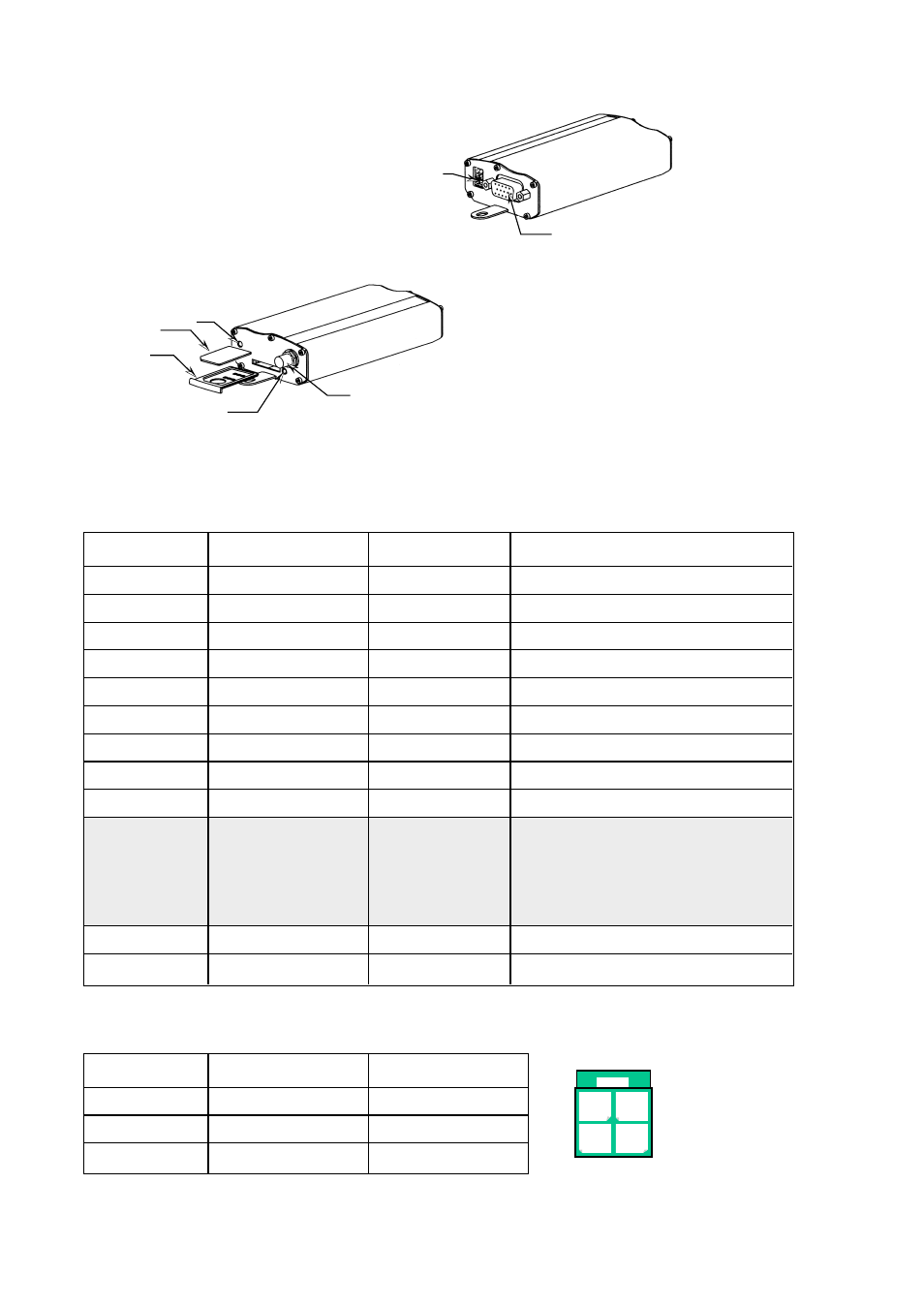
3.1 Terminal connections (DCE)
RS-232/V.24, 15-pin D-sub, female, High density
3.2 Power supply connection
Direction
Connection no.
CCITT
Description
O
1
109
DCD/Data Carrier Detect
O
6
104
RD/Receive Data
I
2103
TD/Transmit Data
I
8
108.2DTR/Data Terminal Ready
–
9
SG/Signal Ground
O
7
107
DSR/Data Set Ready
I
12105
RTS/Request to Send
O
11
106
CTS/Clear to Send
O
13
125
RI/Ring Indicator
Audio
4
Microphone (+)
5
Microphone (–)
10
Speaker (+)
15
Speaker (–)
Boot
3
Boot
Reset
14
Reset
Connector
Connection no.
Supply
4-position
1
+ 5 – 32V DC
Micro-Fit 3.0
20V
3–4
Not in use
Power Supply
5-32V DC
15-pole D-sub connector, female
RS-232/V.24
LED
indication
SIM card
SIM card
holder
Button to eject the
SIM card holder
I = Input on GS-01
O = Output on GS-01
Antenna
SMA connector
1 2
3 4
Advertising