Controls and components, Figure 1, Figure 2 – Allmand Brothers MLEX20-30KW V User Manual
Page 16: Figure 1a
Advertising
16
16
CONTROLS AND COMPONENTS
NOTE:
PHOTOGRAPHS MAY SHOW NON-STANDARD EQUIPMENT AND OPTIONS
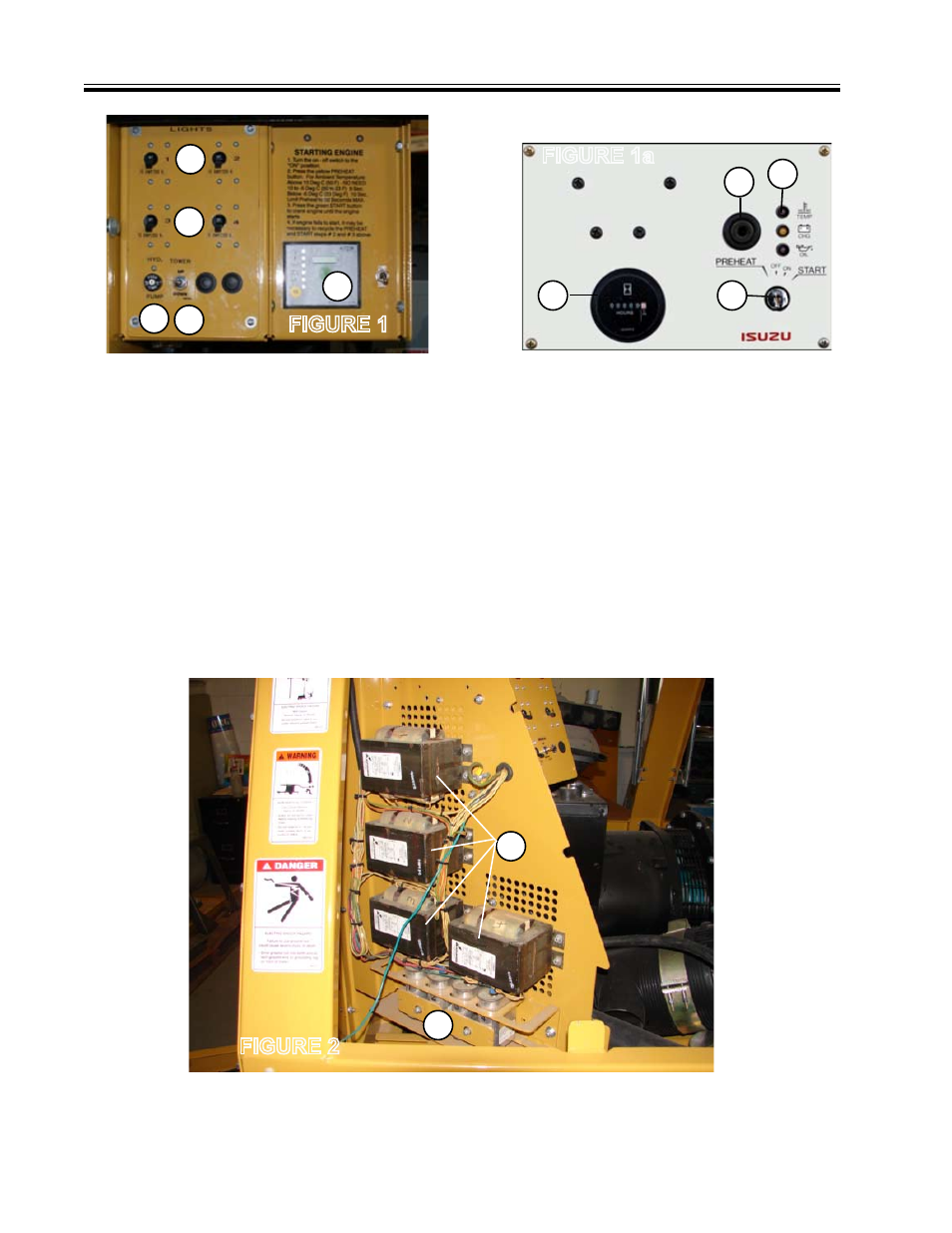
FIG. 1. CONTROL PANEL
(KUBOTA)
1. Switch, Circuit Breaker (Lights 1and 2)
2. Switch, Circuit Breaker (Lights 3 and 4)
3. Engine Control and Operation Panel
FIGURE 1
FIG. 2 BALLAST PANEL
1. Ballast Capacitors 1 through 4
2. Ballast Transformers 1 through 4
FIGURE 2
4. Hydraulic Pump Circuit Breaker
5. Tower UP/DOWN Switch
1
2
3
4 5
1
2
FIGURE 1a
1
2
3
4
FIG. 1a. ENGINE
CONTROL PANEL
(ISUZU)
1. Ignition Switch
2. Glow Plug Indicator
3. Engine Fault Indicator Lights
Coolant temperature
Starting system
Oil pressure
4. Hour Meter
Advertising