H3C Technologies H3C S10500 Series Switches User Manual
Page 21
11
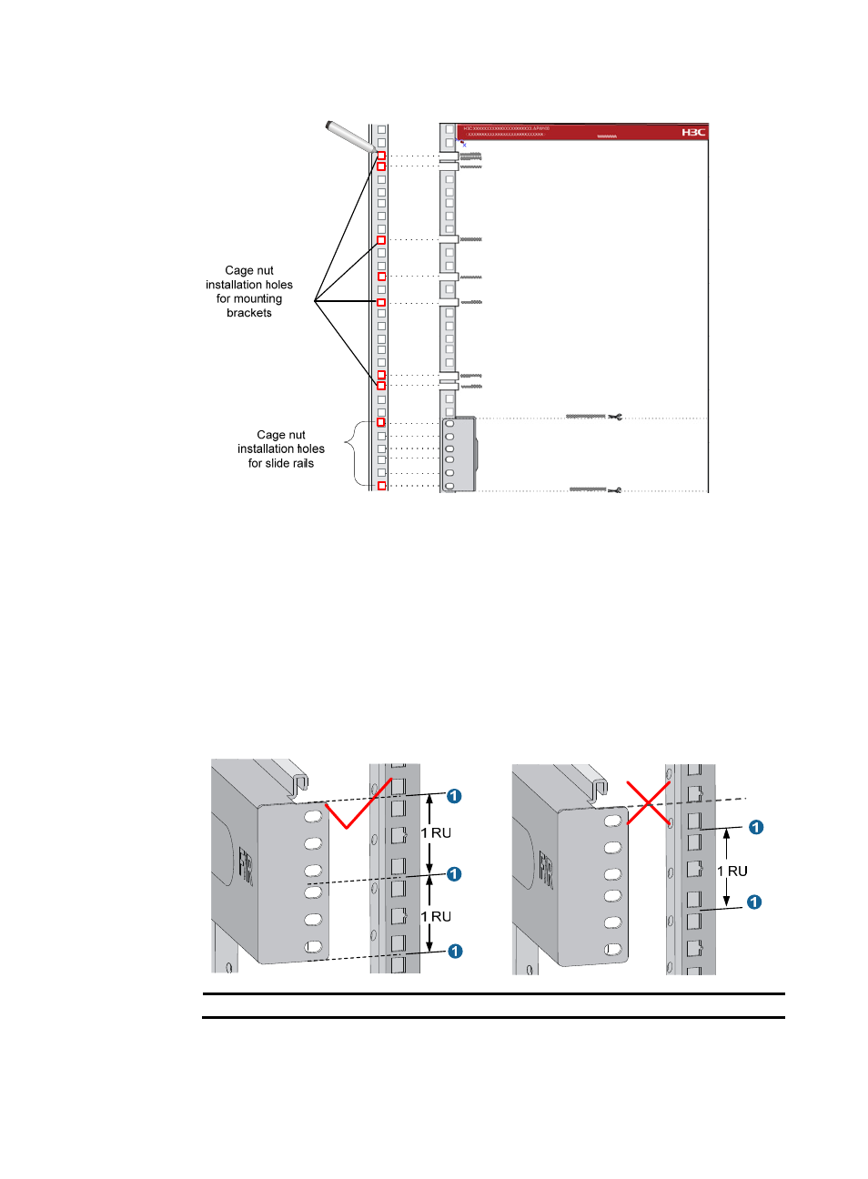
Figure 5 Determining the cage nut installation holes by using the template
{
For the following situations, use a slide rail to determine the cage nut installation holes:
−
For an S10504, S10508, S10508-V, or S10512 switch that uses H3C slide rails.
−
For a switch that uses non-H3C slide rails.
Make sure the bottom edge of a slide rail aligns with the middle of the narrower metal area
between holes on a rack post, as shown in
One rack unit has three holes, the middle of which is an auxiliary installation hole, and the
other two are standard installation holes. You can distinguish them by the space between each
two holes. The space between a standard installation hole and an auxiliary installation hole is
wider than that between two adjacent standard installation holes.
Figure 6 Determining the cage nut installation holes by using a slide rail
(1) Middle of the narrower metal area between holes
3.
Install six cage nuts in the square holes in each rack post, as shown in