Configuration procedure – H3C Technologies H3C S7500E Series Switches User Manual
Page 144
3-62
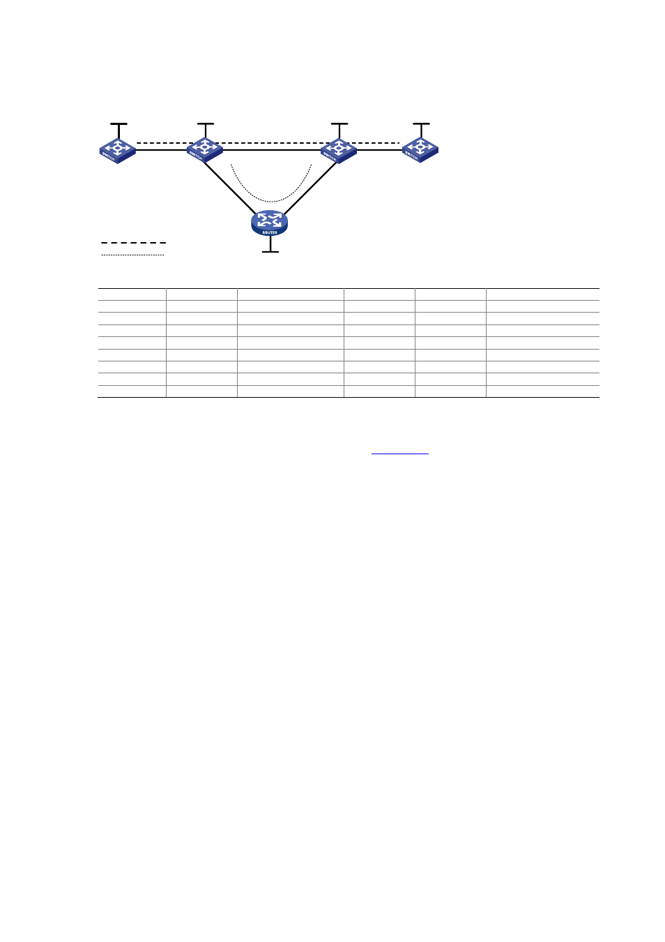
Figure 3-11
Link protection using the FRR approach
Switch A
Switch B
Switch C
Switch D
Switch E
Vlan-int1
Loop0
Loop0
Loop0
Loop0
Vlan-int1
Vlan-int2
Vlan-int2
Vlan-int3
Vlan-int3
Vlan-int4
Vlan-int4
Primary LSP
Bypass LSP
Vlan-int5
Vlan-int5
Loop0
Device Interface IP
address
Device Interface
IP
address
Switch A
Loop0
1.1.1.1/32
Switch E
Loop0
5.5.5.5/32
Vlan-int1
2.1.1.1/24 Vlan-int4
3.2.1.2/24
Switch B
Loop0
2.2.2.2/32
Vlan-int5
3.3.1.1/24
Vlan-int1
2.1.1.2/24 Switch C
Loop0
3.3.3.3/32
Vlan-int2
3.1.1.1/24 Vlan-int3
4.1.1.1/24
Vlan-int4
3.2.1.1/24 Vlan-int2
3.1.1.2/24
Switch D
Loop0
4.4.4.4/32
Vlan-int5
3.3.1.2/24
Vlan-int3
4.1.1.2/24
Configuration procedure
1) Assign IP addresses and masks to interfaces (see
Omitted
2) Configure the IGP protocol
# Enable IS-IS to advertise host routes with LSR IDs as destinations on each node. (Omitted)
Perform the display ip routing-table command on each switch. You should see that all nodes learnt
the host routes of other nodes with LSR IDs as destinations. Take Switch A for example:
<SwitchA> display ip routing-table
Routing Tables: Public
Destinations : 13 Routes : 13
Destination/Mask Proto Pre Cost NextHop Interface
1.1.1.1/32 Direct 0 0 127.0.0.1 InLoop0
2.1.1.0/24 Direct 0 0 2.1.1.1 Vlan1
2.1.1.1/32 Direct 0 0 127.0.0.1 InLoop0
2.2.2.2/32 ISIS 15 10 2.1.1.2 Vlan1
3.1.1.0/24 ISIS 15 20 2.1.1.2 Vlan1
3.2.1.0/24 ISIS 15 20 2.1.1.2 Vlan1
3.3.1.0/24 ISIS 15 30 2.1.1.2 Vlan1
3.3.3.3/32 ISIS 15 20 2.1.1.2 Vlan1
4.1.1.0/24 ISIS 15 30 2.1.1.2 Vlan1
4.4.4.4/32 ISIS 15 30 2.1.1.2 Vlan1
5.5.5.5/32 ISIS 15 20 2.1.1.2 Vlan1
127.0.0.0/8 Direct 0 0 127.0.0.1 InLoop0
127.0.0.1/32 Direct 0 0 127.0.0.1 InLoop0
3) Configure MPLS TE basic capabilities, and enable RSVP-TE and CSPF.
# Configure Switch A.