Configuration procedure – H3C Technologies H3C S7500E Series Switches User Manual
Page 187
4-27
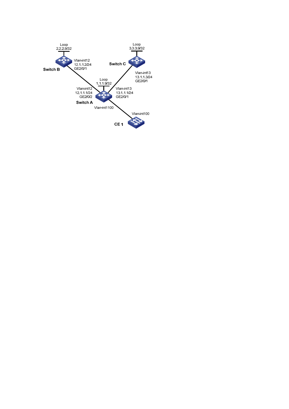
Figure 4-9
Network diagram for configuring BFD in an H-VPLS network for main link detection
Configuration procedure
1) Configure MPLS basic capabilities
# Configure Switch A.
<SwitchA> system-view
[SwitchA] mpls lsr-id 1.1.1.9
[SwitchA] mpls
[SwitchA-mpls] quit
[SwitchA] mpls ldp
[SwitchA-mpls-ldp] quit
[SwitchA] mpls ldp remote-peer switchb
[SwitchA-mpls-ldp-remote-switchb] remote-ip 2.2.2.9
[SwitchA-mpls-ldp-remote-switchb] remote-ip bfd
[SwitchA-mpls-ldp-remote-switchb] quit
[SwitchA] mpls ldp remote-peer switchc
[SwitchA-mpls-ldp-remote-switchc] remote-ip 3.3.3.9
[SwitchA-mpls-ldp-remote-switchc] remote-ip bfd
[SwitchA-mpls-ldp-remote-switchc] quit
[SwitchA] vlan 12
[SwitchA-vlan12] port gigabitethernet 2/0/2
[SwitchA-vlan12] quit
[SwitchA] vlan 13
[SwitchA-vlan13] port gigabitethernet 2/0/1
[SwitchA-vlan13] quit
[SwitchA] interface vlan-interface 12
[SwitchA-Vlan-interface12] mpls
[SwitchA-Vlan-interface12] mpls ldp
[SwitchA-Vlan-interface12] quit
[SwitchA] interface vlan-interface 13
[SwitchA-Vlan-interface13] mpls
[SwitchA-Vlan-interface13] mpls ldp
[SwitchA-Vlan-interface13] quit
# Configure Switch B.
<SwitchB> system-view
[SwitchB] mpls lsr-id 2.2.2.9