Example for configuring hovpn, Network requirements, Configuration procedure – H3C Technologies H3C S7500E Series Switches User Manual
Page 317
6-92
Request time out
Request time out
Request time out
Request time out
--- 130.1.1.1 ping statistics ---
5 packet(s) transmitted
0 packet(s) received
100.00% packet loss
Example for Configuring HoVPN
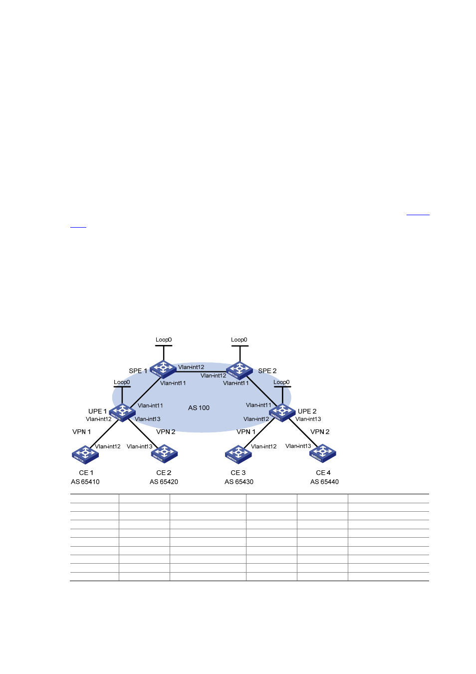
Network requirements
There are two levels of networks, the backbone and the MPLS VPN networks, as shown in
.
z
SPEs act as PEs to allow MPLS VPNs to access the backbone.
z
UPEs act as PEs of the MPLS VPNs to allow end users to access the VPNs.
z
Performance requirements for the UPEs are lower than those for the SPEs.
z
SPEs advertise routes permitted by the routing policies to UPEs, permitting CE 1 and CE 3 in
VPN 1 to communicate with each other and forbidding CE 2 and CE 4 in VPN 2 to communicate
with each other.
Figure 6-25
Configure HoVPN (on switches)
Device Interface IP
address
Device Interface
IP
address
CE 1
Vlan-int12
10.2.1.1/24
CE 3
Vlan-int12
10.1.1.1/24
CE 2
Vlan-int13
10.4.1.1/24
CE 4
Vlan-int13
10.3.1.1/24
UPE 1
Loop0
1.1.1.9/32
UPE 2
Loop0
4.4.4.9/32
Vlan-int11
172.1.1.1/24
Vlan-int11
172.2.1.1/24
Vlan-int12
10.2.1.2/24
Vlan-int12
10.1.1.2/24
Vlan-int13
10.4.1.2/24
Vlan-int13
10.3.1.2/24
SPE 1
Loop0
2.2.2.9/32
SPE 2
Loop0
3.3.3.9/32
Vlan-int11
172.1.1.2/24
Vlan-int11
172.2.1.2/24
Vlan-int12
180.1.1.1/24
Vlan-int12
180.1.1.2/24
Configuration procedure
1) Configure
UPE
1