Capwap dual-link configuration example (on an ac), Network requirements, Configuration procedure – H3C Technologies H3C MSR 50 User Manual
Page 29
1-28
n
[AC-wlan-rp-radpolicy1] quit
# Configure the AP auto configuration feature.
[AC] wlan auto-ap enable
# Configure a common AP for model WA2100 (For each AP model, one common auto AP configuration
is required).
[AC] wlan ap ap1 model WA2100
[AC-wlan-ap-ap1] serial-id auto
# Configure the radio of the common AP.
[AC-wlan-ap-ap1] radio 1 type dot11a
[AC-wlan-ap-ap1-radio-1] max-power 10
[AC-wlan-ap-ap1-radio-1] radio-policy radiopolicy1
[AC-wlan-ap-ap1-radio-1] service-template 1
[AC-wlan-ap-ap1-radio-1] radio enable
CAPWAP Dual-Link Configuration Example (On an AC)
Network requirements
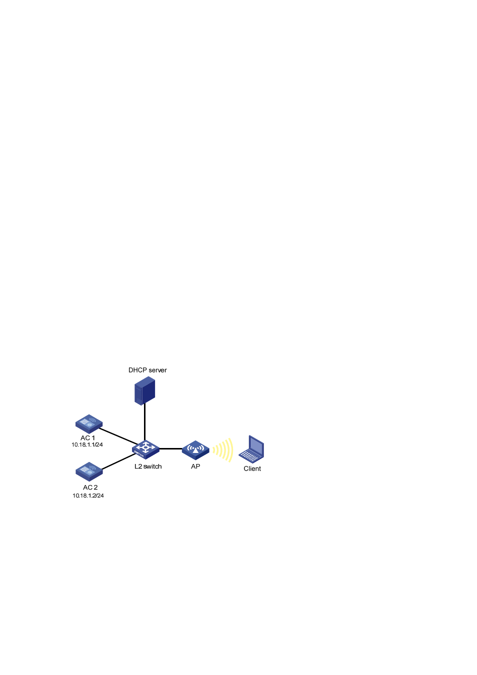
As shown in the following figure, AC1 and AC2 are connected to a L2 switch. An AP is connected to
AC1 and AC2 through the L2 switch. AC1, AC2 and the AP are in the same network. The AP gets its IP
address from the DHCP server. The IP address of AC1 is 10.18.1.1 and the IP address of AC2 is
10.18.1.2. AC1 is working in master mode while AC2 is working in slave mode. When AC2 detects AC1
is down, AC2 will convert its work mode from slave to master. The AP which is connected to AC2
through a slave tunnel will transform the tunnel mode to master and use AC2 as the master AC.
Figure 1-19 CAPWAP dual link configuratio
Configuration procedure
1) Configuration on AC1.
# Define the WLAN ESS interface.
<AC1> system-view
[AC1] interface WLAN-ESS 1
[AC1-WLAN-ESS1] quit
# Define a WLAN service template and bind the WLAN-ESS interface to this service template.