Gpio, The interface, Input – Grass Valley NV9641A v.1.0 User Manual
Page 83: 6 gpio, Chapter 6, Describes the tally, E chapter 6, Ad chapter 6, Topics
73
GPIO
Chapter 6 provides information about the tally (GPIO) interface.
Topics
The Interface
The tally interface includes 8 optically isolated inputs and 4 solid-state relay outputs (also opti-
cally isolated). Tally devices you connect to inputs can trigger events
—
through the NV9641A
—
in the router control system. The router control system can trigger events that
—
through the
relays in the NV9641A
—
switch your tally devices.
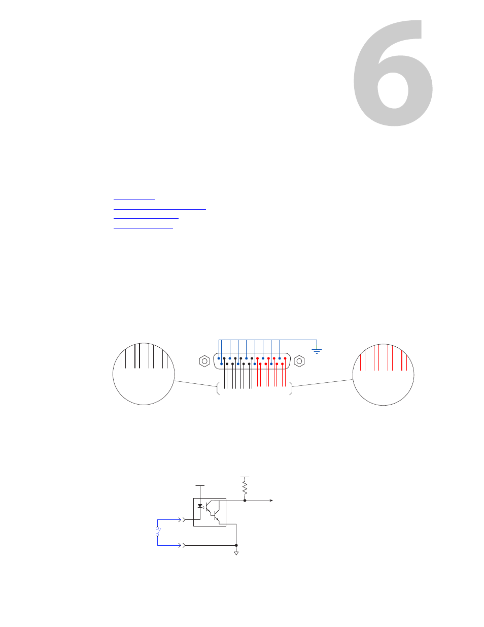
The DB25 connector, labeled “GPI Interface” at the rear of the NV9641A presents the tally
signals. There are 8 input signals and 4 pairs of output signals.
Fig. 6-1: GPI Interface
Input
The tally inputs expect contact closure to ground, through the ground pins on the connector, to
trigger a GPI input event.
Fig. 6-2: GPI Input
+
+
7 6
3 2
13
3
1
25
14
+
2
1
+
0
5 4
Inputs
1 0
Outputs
Ground
+
+
6
3
14
+
2
1
+
0
7 6
3 2 5 4
1 0
+5V
Optical
Isolation
C
E
+5V
Tally Input n
to internal bus
10K
Customers
Switch (or
Equivalent
Logic)