Panel organization, Function buttons, Alphanumeric display – Grass Valley NV9603A v.1.1 User Manual
Page 14: Display fields, Function buttons alphanumeric display
4
Introduction
Panel Organization
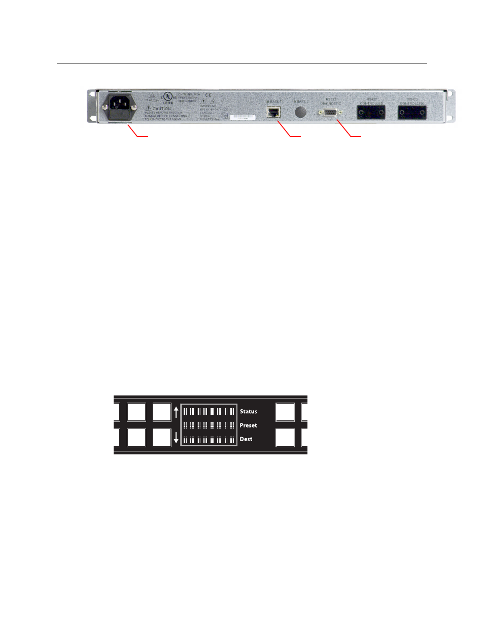
At the rear are power, serial, and network connectors:
Fig. 2-2: NV9603A Rear
The ports labeled 10base2 and RS-422 are non-operational and are covered. Only the serial port
and the Ethernet port are available.
The AC connector has a compartment in which you can find a spare fuse.
(The Ethernet port is 10baseT. The system controller supports 10baseT as well as 100baseT.)
Panel Organization
Function Buttons
The NV9603A has an array of 30 function buttons on the left and 4 function buttons on the right.
Each button has three operational levels: high and low tally (green or amber), and off. Operators
can adjust the low tally levels in increments of 10% using the panel’s menu. Buttons that are
turned off are said to be “dark.” (Physically, they are actually white or gray.)
Generally, green represents a source or a source function and amber represents a destina-
tion or a destination function.
The function buttons each have clear plastic keycaps under which you may place plastic inserts
for button legends. It is a simple matter to change button legends.
Alphanumeric Display
The display has 3 display fields.
Display Fields
The display has 3 fields of 8 characters:
•
Status.
The ‘Status’ field always shows the source that was routed to the currently selected destina-
tion, which is identified in the ‘Destination’ field.
•
Preset.
The ‘Preset’ field shows the source that is pending a take. After the take, this source becomes
the current source and appears in the ‘Status’ field.
Ethernet
Serial port (RS-232)
Power (AC)