Chassis, Midplane, Chassis midplane – Grass Valley PFR 500/E Dec 12 2002 User Manual
Page 18
Chapter 1 About the PFR500/E
18
PFR 500/E Instruction Manual
20 September 2002
Chassis
The chassis is a sheet-metal housing which contains a passive midplane and chassis
slots for the RAID Controllers, or Loop Bypass Boards, disk drives, power supplies,
and the fan modules.
Each chassis includes a chassis address switch on the midplane board that must be set
to a unique address 0 through 9 during installation. Refer to your PVS Series
Installation Guide or the Media Area Network Installation Manual for information on
setting the chassis address switch depending how the PFR 500 is used. See also,
“Chassis address setting requirement” on page 26
.
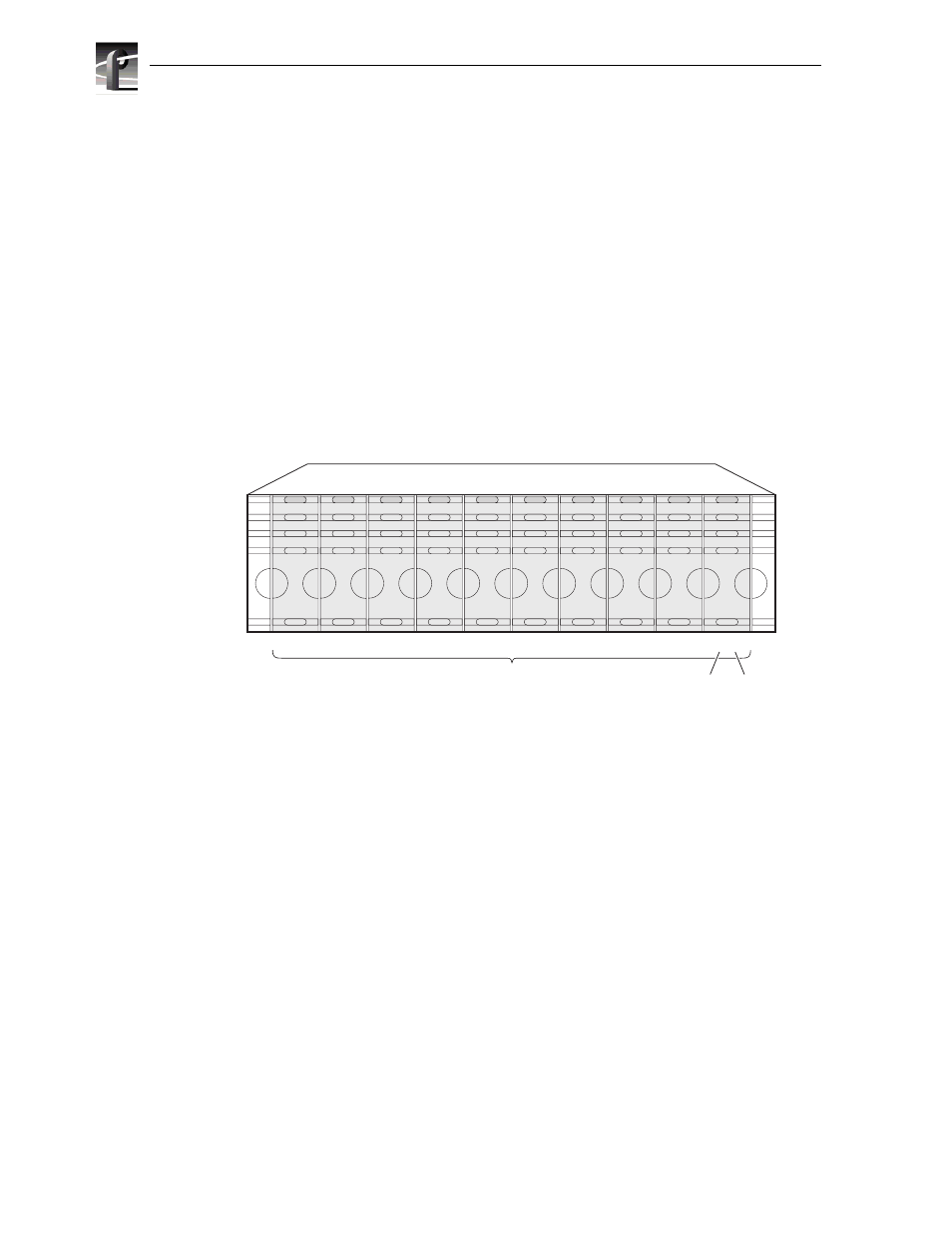
The following diagram shows how disk modules are identified based on the chassis
address and physical location. The chassis with an address set to 0 contains drives
from 0 to 9; the chassis with an address set to 1 contains drives from 10 to 19; and so
forth.
Midplane
The midplane distributes power and signals to all the chassis components. All FRUs
plug directly into midplane connectors. The midplane includes a chassis address
switch that must be set during installation. Refer to
for information on setting the chassis address.
8136-3
n 0
n 1
n 2
n 3
n 4
Disk Modules
PFR500 Front Panel
n 5
n 6
n 7
n 8
n 9
Disk
ID
Chassis
Address