Circuit board modules – Grass Valley PFR 500/E Dec 12 2002 User Manual
Page 20
Chapter 1 About the PFR500/E
20
PFR 500/E Instruction Manual
20 September 2002
Circuit board modules
There are two circuit board modules used: the Loop Bypass Board module (LBB) and
the RAID Controller module. The LBB module contains one Loop Bypass Board
which provides an internal Fibre Channel loop for the disk modules installed in the
chassis. The RAID Controller module also contains a Loop Bypass Board plus a
RAID Controller board used to manage the disk drives and provide a Fibre Channel
interface to the Profile system.
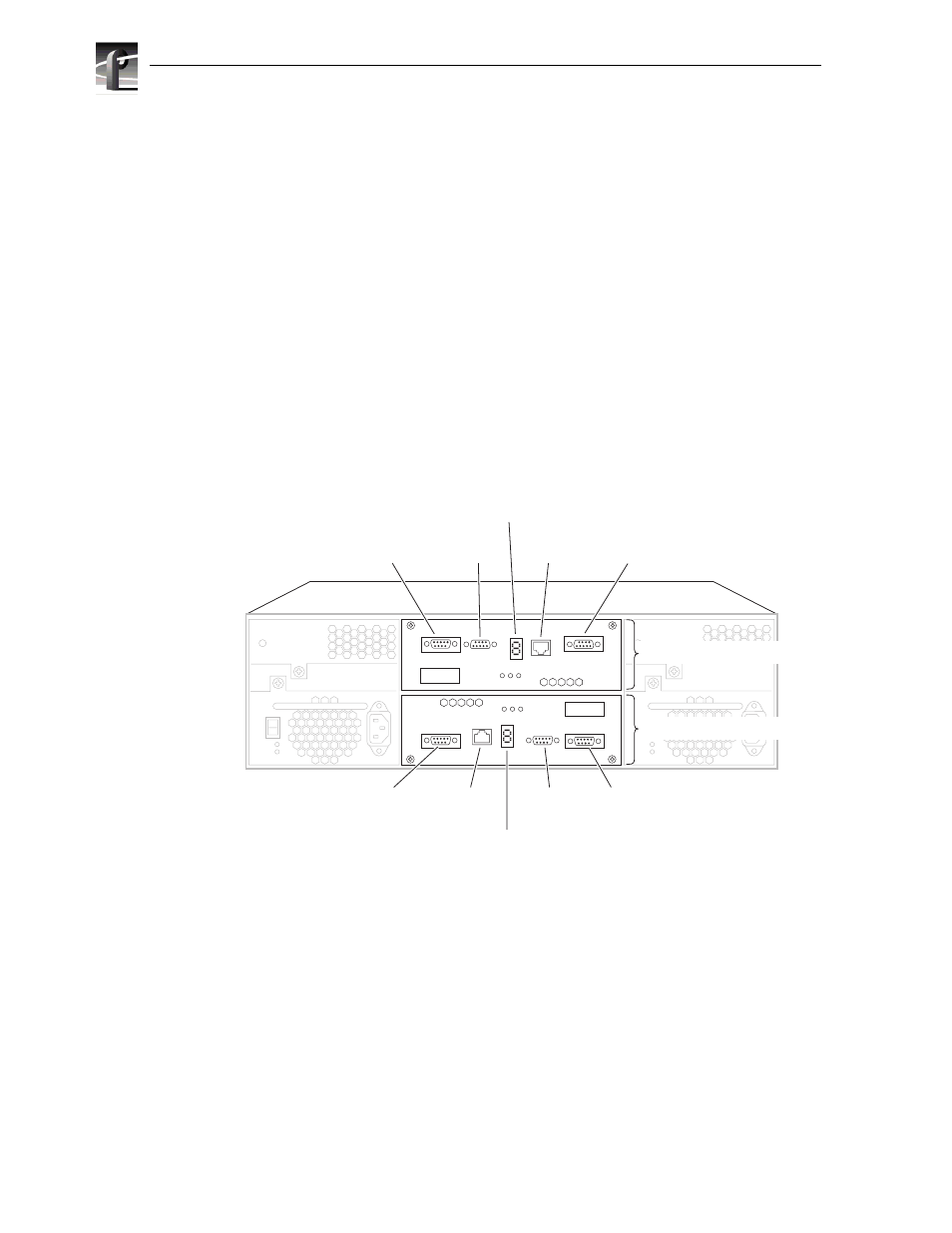
PFR 500E RAID Expansion Chassis circuit board modules
PFR500E RAID Expansion Chassis always has two LBB modules installed as shown
in the following figure. This provides two internal Fibre Channel loops for the disk
modules. At power-up, odd numbered disk drives are supported by the LBB in the ‘A’
slot, while even numbered disk drives are supported by the LBB in the ‘B’ slot. In the
event of an LBB module failure, the faulty loop is bypassed and all disk drives
failover to the remaining LBB module. The LBBs are clearly labeled “A” or “B” on
the rear panel of the canister.
The LBB in the PFR 500E has two Fibre Channel ports: the Left and Right Fibre
Channel Loop Ports. Copper GBICs (Gigabit Interface Converter) are used in these
ports to connect Fibre Channel cabling to a PFR500 or PFR500E. This extends the
Fibre Channel loop of the corresponding PFR500/E chassis. There is a port status
LED for each Fibre Channel port. Refer to
“Interpreting rear panel status LEDs” on
7 Segment LED
(displays chassis address)
7 Segment LED
(displays chassis address)
8136-2
Serial
Port
Serial
Port
Ethernet
Port
Ethernet
Port
Left
Fibre Channel
Loop Port
Right
Fibre Channel
Loop Port
Right
Fibre Channel
Loop Port
Left
Fibre Channel
Loop Port
Loop Bypass Board B
PFR500E
Loop Bypass Board A