Grass Valley XtenDD DD User Manual
Page 94
5. Connection and Statup
5 - 32
Planning and Installation - Rev. 3 / 04.2005
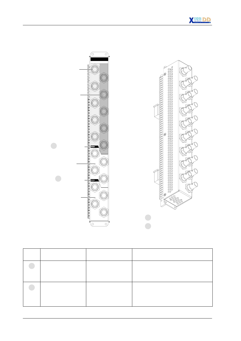
5.5.1.4 Aux Outputs
PGM
23 / 31
1 / 11
OUTPUT MODULE RY 3005 / 1
25 / 33
27 / 35
26 / 34
PVW
CLEAN
PGM
9 / 19
4 / 14
8 / 18
3 / 13
7 / 17
2 / 12
6 / 16
AUX
5 / 15
21 / 29
PVW
22 / 30
CLEAN
P/P (M/E 3)
M/E 1 (M/E 2)
PGM
24 / 32
OUTPUT 1 / 2
28 / 36
PGM
10 / 20
1 - 5 Aux bus outputs for
Output Processor RY 3030*
1 - 10 Aux bus outputs for
Output Processor RY 3031*
21 - 24 M/E 1 outputs *
25 - 28 P/P outputs *
8
21
20
9
OUTPUT MODULE RY 3005 / 2
*
Example for 1 M/E and P/P configuration (SH-2-BM)
Item
No.:
Socket / Connector
Description
Socket type
Connector type
Function
8
1 - 10 and 21 - 28
Outputs
BNC / Serial Comp / HD
SMPTE 292
5 (10) auxiliary outputs and direct M/E 1 and
P/P outputs.
Designation “Aux 1 - Aux 10” at first output
module.
9
11 - 20 and 29 - 36
Outputs
BNC / Serial Comp / HD
SMPTE 292
5 (10) auxiliary outputs and direct M/E 2 and
M/E 3 outputs.
Designation “Aux 11 - Aux 20” at second
output module.