Grounding diagram, 6 grounding diagram, Machine-encoders – HEIDENHAIN TNC 122 Technical Manual User Manual
Page 10
Advertising
4/97
TNC 122
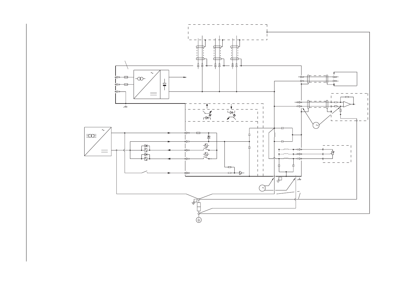
6 Grounding Diagram
9
6 Grounding Diagram
C
C
L
X41/22
6mm
2
6mm
2
6mm
2
6mm
2
X51
0
1
0,1A
0,1A
0V
+24V
-
X41/33
X41/9
0V
+24V-
3
1
C
C
C
V
L
V
3
2
1
X1
X2
X3
0V
SI
6mm
2
B
B
SI
L1
N
PE
X41
X41/10
X41
C
0V
TNC 122
Adapter
V.24
X21
X41/48
X41/24
X41/47
X41/23
SI
If nominal value input is grounded,
a ground loop will result. Therefore
be sure that 0 V and ground wire
are short and configured for low noise.
16 inputs
EMERGENCY STOP
15 outputs
Test point 1
(Fault voltg. 0V/
housing)
Optoc.
Test point 2
(Fault voltg. with
grounded nominal
value input)
Machine-Encoders
Motor controller
with nominal value
difference input
Line voltage
100 - 240V
Line frequency
50 - 60 Hz
stab. power
supply
PLC supply voltage
with basic insulation
Pot. for
feed rate
Advertising