Ii – 4 d a ta int e rf ace – HEIDENHAIN PT 880 User Manual
Page 132
132
II Technical Information
II – 4 D
a
ta Int
e
rf
ace
Wiring the connecting cable
The wiring of the connecting cable depends on the device being
connected (see technical documentation for external device).
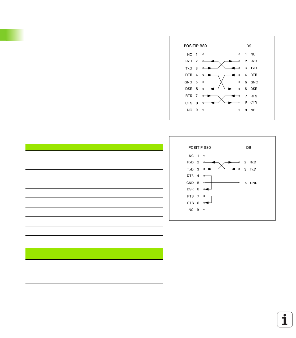
Full wiring
Before the POSITIP 880 and your PC can communicate, they need to
be connected to each other with a serial cable. See Fig. II.25 & Fig.
II.26.
Pin assignment
Signal
Fig. II.25 Pin connection for serial port with
handshaking
Fig. II.26 Pin connection for Serial Port without
handshaking
Pin
Assignment
1
No assignment
3
TXD
- Transmitted data
2
RXD
- Received data
7
RTS
- Request to send
8
CTS
- Clear to send
6
DSR
- Data set ready
5
SIGNAL GND
- Signal ground
4
DTR
- Data terminal ready
9 No
assignment
Signal
Signal level
“1“= “active“
Signal level
“0“= “inactive“
TXD, RXD
-3 V to -15 V
+ 3 V to + 15 V
RTS, CTS
DSR, DTR
+ 3 V to + 15 V
-3 V to -15 V