Non-heidenhain devices – HEIDENHAIN iTNC 530 (606 42x-01) User Manual
Page 670
670
Tables and Overviews
1
8
.2 Pin La
y
outs and Connecting Cables f
o
r the D
a
ta Int
e
rf
aces
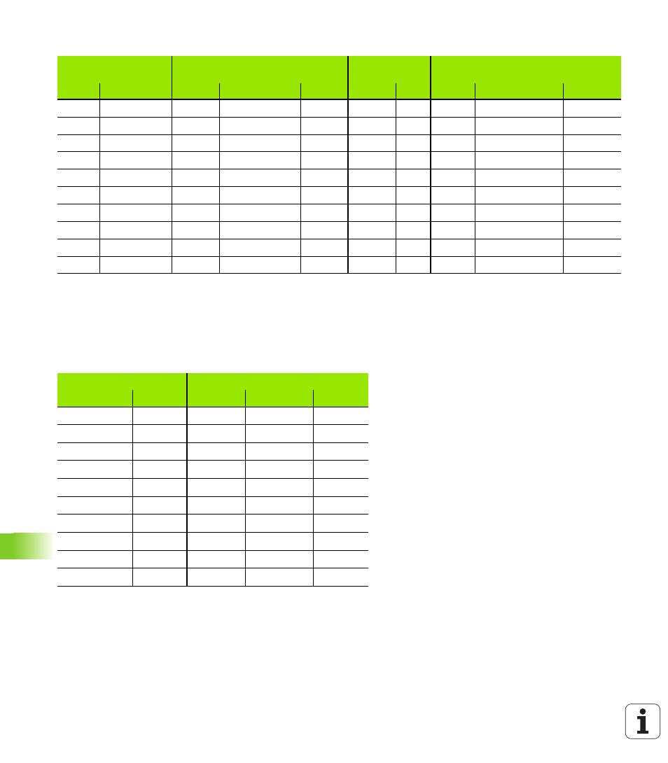
When using the 9-pin adapter block:
Non-HEIDENHAIN devices
The connector layout of a non-HEIDENHAIN device may substantially
differ from the connector layout of a HEIDENHAIN device.
It depends on the unit and the type of data transfer. The table below
shows the connector pin layout on the adapter block.
TNC
Connecting cable 355 484-xx
Adapter block
363 987-02
Connecting cable 366 964-xx
Male
Assignment
Female
Color
Male
Female
Male
Female
Color
Female
1
Do not assign
1
Red
1
1
1
1
Red
1
2
RXD
2
Yellow
2
2
2
2
Yellow
3
3
TXD
3
White
3
3
3
3
White
2
4
DTR
4
Brown
4
4
4
4
Brown
6
5
Signal GND
5
Black
5
5
5
5
Black
5
6
DSR
6
Violet
6
6
6
6
Violet
4
7
RTS
7
Gray
7
7
7
7
Gray
8
8
CTS
8
White/Green
8
8
8
8
White/Green
7
9
Do not assign
9
Green
9
9
9
9
Green
9
Hsg.
Ext. shield
Hsg.
Ext. shield
Hsg.
Hsg.
Hsg.
Hsg.
Ext. shield
Hsg.
Adapter block 363 987-02
Connecting cable 366 964-xx
Female
Male
Female
Color
Female
1
1
1
Red
1
2
2
2
Yellow
3
3
3
3
White
2
4
4
4
Brown
6
5
5
5
Black
5
6
6
6
Violet
4
7
7
7
Gray
8
8
8
8
White/Green
7
9
9
9
Green
9
Hsg.
Hsg.
Hsg.
Ext. shield
Hsg.