4 installing the power supply assembly, 1 installing the power supply assembly, Installing the power supply assembly – SMA External Supply Voltage 230 V User Manual
Page 26
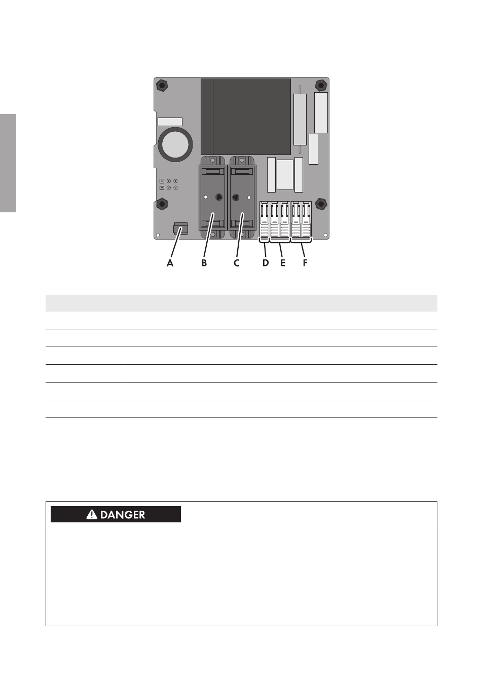
Connection area of the power supply assembly:
Figure 11 : Connection area of the power supply assembly
Position
Designation
A
Alarm contact for the status of the surge arrester
B
Base for the surge arrester of the line conductor
C
Base for the surge arrester of the neutral conductor
D
Terminal X22:1 for functional grounding
E
Terminal X22:2,3 for incoming supply voltage
F
Terminal X22:1,2 for outgoing supply voltage
4.4
Installing the Power Supply Assembly
4.4.1
Installing the Power Supply Assembly
To enable supply voltage to be laid from one SMA String-Monitor to the next, the power supply
assembly is equipped with two terminals, each for line conductor and neutral conductor.
Danger to life from electric shock due to live voltage
High voltages are present in the live components of the DC sub-distribution. Touching live
components results in death or serious injury due to electric shock.
• Disconnect the inverter on the DC side (see the inverter manual).
• Disconnect the DC sub-distribution (see the DC sub-distribution manual).
• Disconnect all DC sub-distributions that are connected in parallel in the DC connection area
(see the manual of the respective DC sub-distribution).
4 Installation
SMA Solar Technology AG
Installation Manual
SSMU-AUX-PB/OVP-IA-xx-10
26
ENGLISH