SMA WB 5000 Installation User Manual
Page 41
SMA
Technology AG
Communication
Installation Guide
WB50_60-11:SE4005
Page 41
9.
Now connect the next Windy Boy.
10. Connect the conductors of the cable to the next inverter, using the same
terminals as you noted when connecting the first Windy Boy. This applies to the
cable conductors coming from the final Windy Boy and also to those leading to
the next Windy Boy. Be especially careful here. Finding cabling mistakes can be
very time consuming.
11. Repeat steps 9 and 10 for every Windy Boy that is to be connected to the
system.
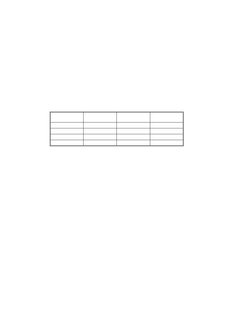
12. For subsequent connection of a PC, or a Sunny Boy Control with an interface
converter, the cable ends should be labelled as follows:
The connection of one or more Windy Boys to a Sunny Boy Control using RS485 is
described in detail in the Sunny Boy Control user manual.
Terminal
D-SUB 9 plug
Conductor
labelling
Your conductor
label
Case
Case
Shield
2
3
Data +
7
8
Data -
5
5
GND