Yaskawa DS387 User Manual
Page 10
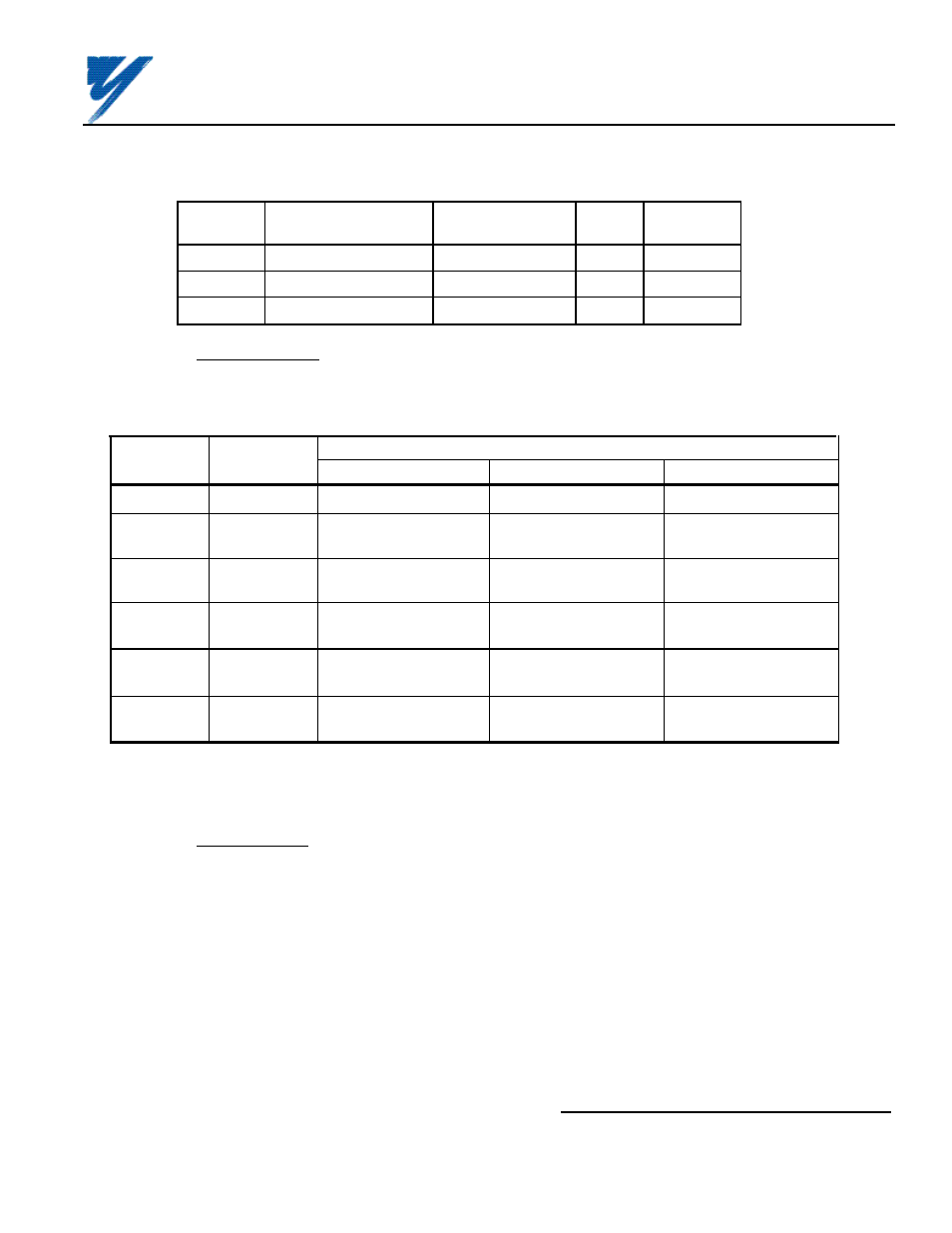
Table B3. Setting Gain of Speed Reference Commands
Constant
Setting
Incre-
Factory
No.
Description
Range
ment
Setting
Cn-30
AI-14B Chan. 1 Gain
0.0 to 1000.0 (%)
0.1
100.0
Cn-31
AI-14B Chan. 2 Gain
0.0 to 1000.0 (%)
0.1
100.0
Cn-32
AI-14B Chan. 3 Gain
0.0 to 1000.0 (%)
0.1
100.0
B8. Reinstall and secure drive cover.
B9. Place this instruction sheet with the drive technical manual.
THIS COMPLETES INSTALLATION OF THIS OPTION IN THE VCD 703.
(2) Reference Inputs:
The AI-14B can be programmed for either speed mode references or torque
mode references by programming Sn-25; see Table B4.
(3) Monitor Display:
Inputs to the AI-14B can be monitored by the VCD 703 by using the Un-XX
constants.
Un-36 = CH1 input voltage (V)
10V / 10V
Un-37 = CH2 input voltage (V)
10V / 10V
Un-38 = CH3 input voltage (V)
10V / 10V
Table B4. Selecting Speed or Torque Mode
SET
CONTROL
AI-14B INPUTS
VALUE
MODE *
CH 1
CH 2
CH 3
0000
ASR I
Speed Reference
Not Used
Not Used
0001
ASR II
Speed Reference
Speed Ref.
Torque
Trim
Compensation
0010
ASR III
Speed Reference
Fwd. Torque Limit
Rev. Torque Limit
(TLF)
(TLR)
0011
ASR IV
Speed Reference
Torque Limit
Torque
(TLF, TLR)
Compensation
1000
ATR I
Speed Limit
Torque
Torque
Reference
Compensation
1001
ATR II
Not Used
Torque
Not Used
Reference
* ASR : Speed control mode; ATR : Torque control mode
NOTE: To increase control accuracy, use a high-accuracy, stabilized power supply.
Yaskawa Electric America, Inc-www.drives.com
02Y00025-0296 Page 10 OF 14
REL. 08/23/91
ANALOG SPEED REFERENCE
(BIPOLAR) (AI-14B) MODEL DS387