Yaskawa DS387 User Manual
Page 7
Section B: Installation in a VCD 703
INTRODUCTION
When installed, this option allows the user to interface three separate high resolution voltage signals (13-bit plus
sign). These signals can be programmed for speed reference, torque reference, torque limit, or torque comp.
Gain for the input signals is adjusted by using drive constants. Polarity (sign) of the speed reference controls
direction of motor rotation.
INSTALLATION
B1. Disconnect all electrical power to drive.
B2. Remove drive front cover. Check that CHARGE indicator lamp inside drive is off.
B3. Verify voltage has been disconnected by using a voltmeter to check for voltage at incoming power terminals
(L1, L2, L3).
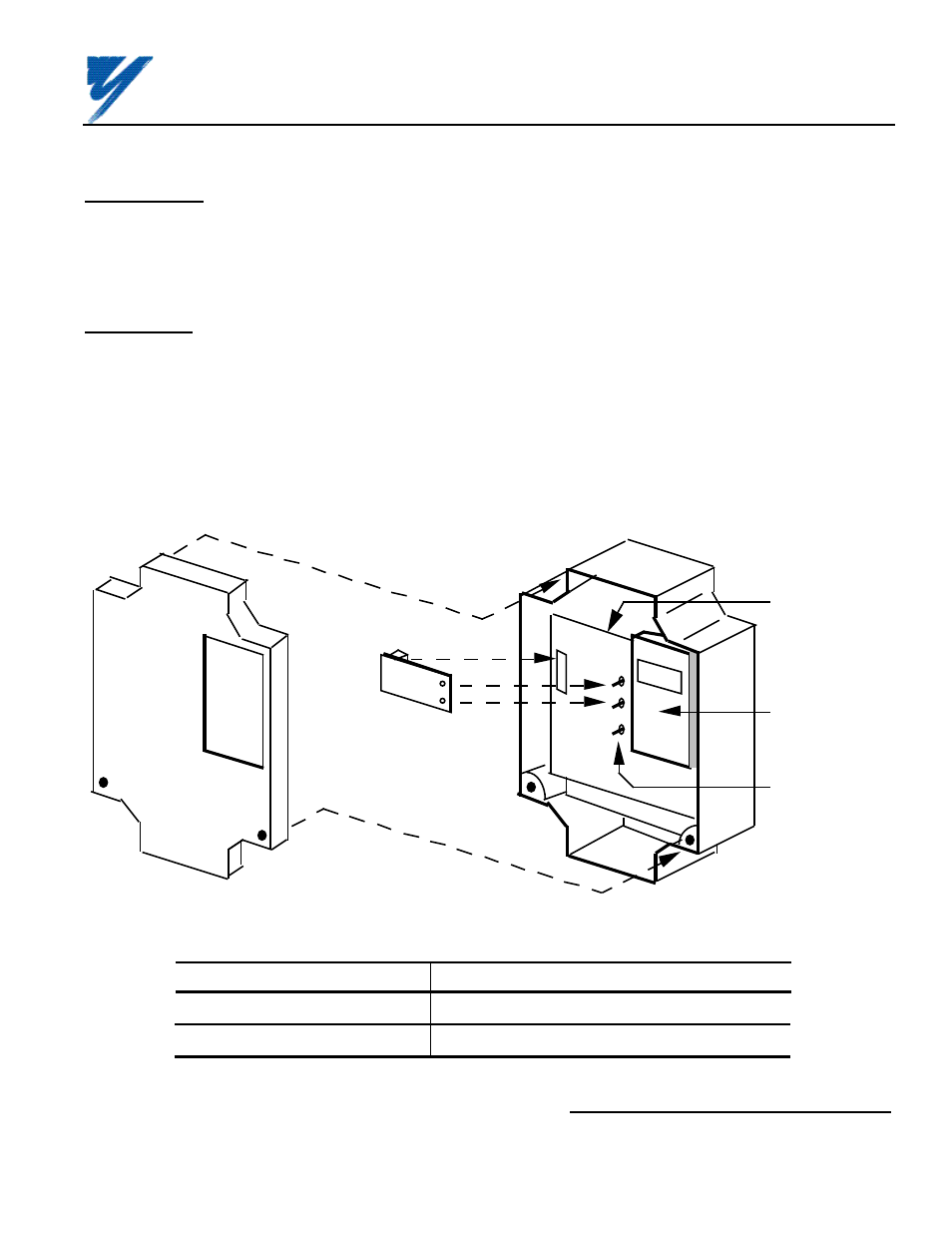
B4. See Figure B1. Install the option on the Main Control Board, 1PCB, and ensure 2CN is properly connected.
Make sure Electrostatic procedure is followed.
Figure B1. Installation of Analog Speed Reference (AI-14B) in VCD 703
Table B1. AI-14B Specifications in VCD 703
Parameter
Value
Input Signal Level
0 to ±10V DC (Input Impedance: 20k
Ω
)
Input Resolution
Voltage: 13 bits (1/8192) plus sign (polarity)
Yaskawa Electric America, Inc-www.drives.com
02Y00025-0296 Page 7 OF 14
REL. 08/23/91
FRONT
COVER
AI-14B
OPTION
BOARD
DIGITAL
OPERATOR
MAIN
CONTROL
BOARD
PLASTIC
STANDOFFS
ON MAIN
BOARD
2CN
ANALOG SPEED REFERENCE
(BIPOLAR) (AI-14B) MODEL DS387