Yaskawa DS387 User Manual
Page 14
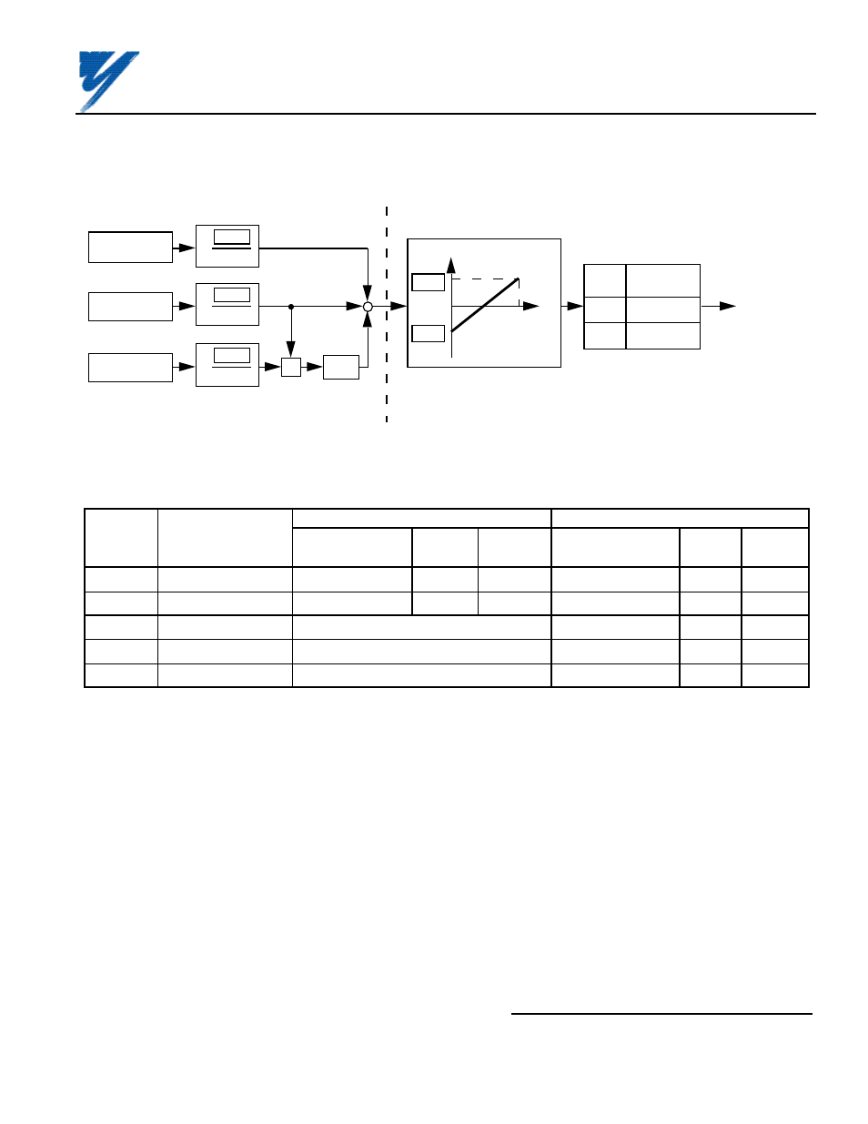
Channel 2 (TC2)
0 to ±10V
Channel 1 (TC1)
0 to ±10V
Channel 3 (TC3)
0 to ±10V
Cn-46
100
x
Cn-45
100
x
Cn-47
100
x
x
1/10
( AI-14B )
( GPD 503 )
+
+
+
bn-05
bn-06
Frequency Reference (%)
Input Voltage
10V
Sn-25
Frequency
Reference
0000
0001
+ / – input
+ input only
Internal
Frequency
Command
Figure 5. Frequency Command Gain and Bias Adjustments
Table 3. Setting Bias and Gain of Frequency Command
LHP GPD 503
HHP GPD 503
Constant
Setting
Incre-
Factory
Setting
Incre-
Factory
No.
Description
Range
ment
Setting
Range
ment
Setting
bn-05
Freq. Reference Gain
0.0 to 1000.0 (%)
1.0
100.0
0.0 to 1000.0 (%)
0.1
100.0
bn-06
Freq. Reference Bias
-100 to 100 (%)
1
0
–100.0 to 100.0 (%)
0.1
0.0
Cn-45
AI-14B Chan. 1 Gain Constant not used; Fixed gain of 100%
0.0 to 1000.0 (%)
0.1
100.0
Cn-46
AI-14B Chan. 2 Gain Constant not used; Fixed gain of 10%
0.0 to 1000.0 (%)
0.1
10.0
Cn-47
AI-14B Chan. 3 Gain Constant not used; Fixed gain of 10%
0.0 to 1000.0 (%)
0.1
10.0
EXAMPLE:
With all channel inputs at maximum, the frequency command (displayed on Digital
Monitor) is only 59 Hz. To obtain 60 Hz maximum frequency command, the required
correction factor (Gain) is 60 Hz/59 Hz = 1.01695 = 101.7%. Therefore, program
bn-05 setting to 101.7 (%).
C8. Reinstall and secure drive cover.
C9. Place this instruction sheet with the drive technical manual.
THIS COMPLETES INSTALLATION OF THIS OPTION IN THE GPD 503.
Yaskawa Electric America, Inc-www.drives.com
02Y00025-0296 Page 14 OF 14
REL. 08/23/91
ANALOG SPEED REFERENCE
(BIPOLAR) (AI-14B) MODEL DS387