Warning – Yaskawa DS387 User Manual
Page 4
IMPORTANT
Because the analog speed reference is converted by 1/16384 resolution, the
voltage source accuracy of the analog speed reference source must be con-
sidered. To ensure speed control accuracy, use a high precision power supply for
the voltage source.
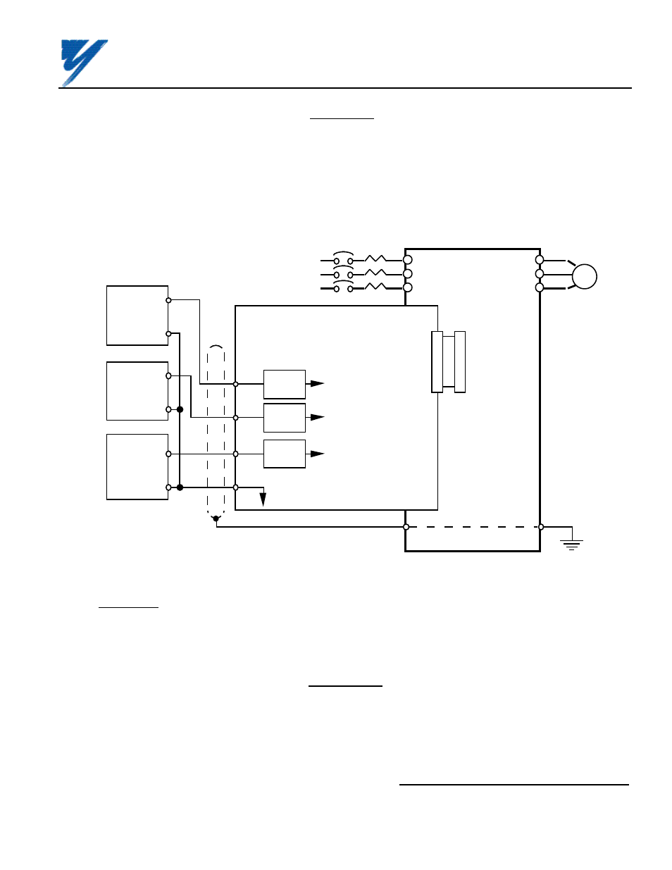
Route wires from the drive and connect to the peripheral device. Refer to "Electrical Installation" in the drive
technical manual for further information on use of shielded cable.
Figure A3. Interconnection for Analog Speed Reference (AI-14B) Circuit in GPD 515
2CN
12
GPD
515
AI-14B BOARD
L1
L2
L3
T1
T2
T3
E
I M
MOTOR
MCCB
SHIELD
0V
HIGH ACCURACY
VOLTAGE / CURRENT
DEVICES
0V
2CN
14 BIT
A/D
14 BIT
A/D
14 BIT
A/D
SEE
FIGURE A4
FOR BLOCK
DIAGRAM
0-±10V
or 0-20mA
0V
0-±10V
or 0-20mA
0-±10V
or 0-20mA
0V
TC1
TC2
TC3
TC4
A7. Adjustments.
There are no adjustments to be made on the Analog Speed Reference option; however, the GPD 515 will have to
be reprogrammed for the input requirement(s) of the remote device and the reversing or non-reversing
requirement of the specific application.
WARNING
IF THE APPLICATION REQUIRES THAT REVERSE MOTOR
ROTATION BE PROHIBITED, PARAMETER b1-04 MUST BE SET
TO " 1 " SO THAT THE MOTOR WILL STOP ANY TIME
POLARITY OF THE SPEED REFERENCE GOES NEGATIVE.
Yaskawa Electric America, Inc-www.drives.com
02Y00025-0296 Page 4 OF 14
REL. 08/23/91
ANALOG SPEED REFERENCE
(BIPOLAR) (AI-14B) MODEL DS387